Editorial Technical Reference

HVAC Unit

This page explains how HVAC Unit is classified within Repair and Installation of Machinery and Equipment. Technical values and manufacturer relationships are research references; confirm the current specification and supplier evidence for each order.

Technical Definition & Core Assembly

A self-contained system for heating, ventilation, and air conditioning that regulates indoor environmental conditions.
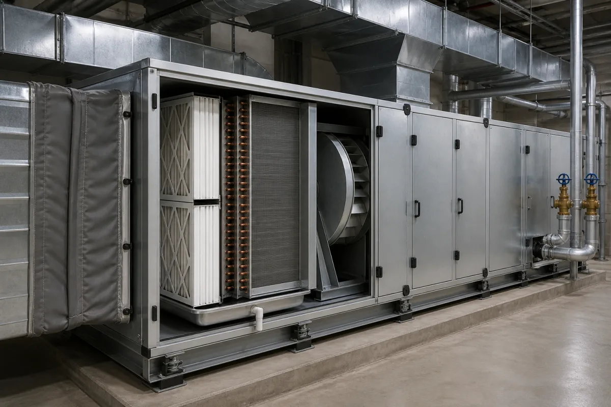
Representative product image. Confirm appearance and specifications with the manufacturer.

Product Specifications

Technical details and manufacturing context for HVAC Unit

Definition
An HVAC unit is a critical component of an Environmental Control System that provides thermal comfort and acceptable indoor air quality by controlling temperature, humidity, and air circulation. It integrates heating, cooling, ventilation, and filtration functions into a single packaged system or split configuration to maintain specified environmental parameters within controlled spaces. This directory entry covers HVAC units used in the repair and installation of machinery and equipment, typically as replacement parts or for new installations. The unit operates by circulating refrigerant through a closed-loop system. In cooling mode, it absorbs heat from indoor air via an evaporator coil and releases it outdoors through a condenser coil. In heating mode, the process reverses or utilizes electric resistance heating or heat pump technology. Air is continuously drawn in, filtered, conditioned (heated/cooled), and distributed through ductwork while maintaining proper ventilation rates. Key selection inputs include cooling and heating capacity (5–100 kW and 5–120 kW respectively, per ISO 5151), airflow rate (1000–20000 m³/h, per ISO 580), operating pressure (1.0–1.6 MPa), supply voltage (380 V AC ±10%, three-phase, 50/60 Hz, per IEC 60038), power consumption (2–50 kW), operating temperature range (-10 to 50 °C, per ISO 5151), refrigerant type (R410A, with R32 available on request, per ISO 817), noise level (55–75 dB(A), per ISO 3744), IP rating (IP54–IP65, per IEC 60529), weight (150–1500 kg), and dimensions (width 800–3000 mm). Materials typically include galvanized steel, copper tubing, aluminum fins, insulation materials, and electrical components. Verification questions should confirm model-specific values and standards with the legal manufacturer or supplier. Maintenance signals include reduced airflow, unusual noise, or refrigerant leaks. Failure boundaries include operation outside specified temperature or pressure limits, which can cause component damage. Always verify the actual model's specifications and applicable standards before procurement or installation.
Working Principle
The HVAC unit operates by circulating refrigerant through a closed-loop system. In cooling mode, it absorbs heat from indoor air via an evaporator coil and releases it outdoors through a condenser coil. In heating mode, the process reverses or utilizes electric resistance heating or heat pump technology. Air is continuously drawn in, filtered, conditioned (heated/cooled), and distributed through ductwork while maintaining proper ventilation rates.
Common Materials
Galvanized steel, Copper tubing, Aluminum fins, Insulation materials, Electrical components
Technical Parameters
ParameterTypical rangeNotes & selection driver
Cooling Capacity5–100 kWSelect based on room heat loadISO 5151
Heating Capacity5–120 kWFor heat pump modelsISO 5151
Airflow Rate1000–20000 m³/hEnsure adequate ventilationISO 580
Operating Pressure1.0–1.6 MPa
Supply Voltage380 ±10% V ACThree-phase, 50/60 HzIEC 60038
Power Consumption2–50 kWCheck electrical supply capacity
Operating Temperature-10–50 °COutdoor unit limitsISO 5151
RefrigerantR410AR32 available on requestISO 817
Noise Level55–75 dB(A)Indoor/outdoor unitsISO 3744
IP RatingIP54–IP65Outdoor units require IP65IEC 60529
Weight150–1500 kgConsider structural support
Dimensions (W×D×H)800–3000 mmWidth range; check clearance

Ranges are indicative industry figures for RFQ preparation, not a supplier commitment. Confirm every value and standard with the legal manufacturer before ordering.

Components / BOM
  • Compressor
    Circulates refrigerant through the system by increasing pressure and temperature
    Material: Cast iron/steel housing with copper windings
  • Evaporator Coil
    Absorbs heat from indoor air as refrigerant evaporates
    Material: Copper tubing with aluminum fins
  • Condenser Coil Part
    Releases heat to outdoor air as refrigerant condenses
    Material: Copper tubing with aluminum fins
  • Blower Fan
    Circulates air across coils and through ductwork
    Material: Galvanized steel housing with aluminum blades
  • Air Filter Part
    Removes particulates and contaminants from circulated air
    Material: Fiberglass or pleated media
  • Control Board
    Manages system operation, temperature regulation, and safety functions
    Material: PCB with electronic components

Applied To / Applications

This component is essential for the following industrial systems and equipment:

Industrial Ecosystem & Supply Chain Structure

Complementary Systems
Downstream Applications
Specialized Tooling

Application Fit & Sizing Matrix

Operational Limits
pressure: Up to 500 Pa static pressure
flow rate: 1000 to 10000 CFM
other spec: Humidity range: 20% to 80% RH
temperature: -20°C to 50°C ambient, 15°C to 30°C supply air
Media Compatibility
✓ Standard air (office environments) ✓ Cleanroom air (filtered environments) ✓ Commercial building air (retail/hospitality)
Unsuitable: Corrosive or explosive atmospheres (chemical plants, refineries)
Sizing Data Required
  • Total cooling/heating load (BTU/hr or kW)
  • Required airflow (CFM or m³/h)
  • Space dimensions and occupancy (sq ft, ceiling height, people count)

Reliability & Engineering Risk Analysis

Failure Mode & Root Cause
Compressor Failure
Cause: Refrigerant contamination, lubrication breakdown due to moisture ingress or thermal degradation, electrical winding insulation failure from voltage spikes or overheating
Coil Fouling and Corrosion
Cause: Accumulation of dirt, dust, biological growth (mold/algae) on evaporator or condenser coils reducing heat transfer efficiency; galvanic or pitting corrosion from chemical exposure, moisture, and improper material selection
Maintenance Indicators
  • Unusual grinding, screeching, or rattling noises from the compressor or blower assembly indicating mechanical wear or imbalance
  • Significant reduction in cooling/heating capacity accompanied by ice formation on coils or refrigerant lines, suggesting refrigerant leaks or airflow obstruction
Engineering Tips
  • Implement a proactive coil cleaning schedule using appropriate chemical cleaners and low-pressure water rinsing to maintain heat transfer efficiency and prevent corrosion
  • Install and regularly monitor refrigerant moisture indicators and oil analysis systems to detect contamination early, and ensure proper electrical protection (surge suppressors, correct voltage supply) for compressor longevity

Indicative industry ranges for design and RFQ preparation. Confirm the exact figures and applicable standard with the manufacturer before specifying.

Compliance & Manufacturing Standards

Applicable Standards
ISO 16890:2016 - Air filters for general ventilation ANSI/ASHRAE 62.1-2022 - Ventilation for Acceptable Indoor Air Quality EN 14511:2022 - Air conditioners, liquid chilling packages and heat pumps

Quoted from the published standard.

Manufacturing Precision
  • Coil tube diameter: +/-0.05mm
  • Fan blade balance: 0.1mm maximum runout
Quality Inspection
  • Airflow performance test (ANSI/AMCA 210)
  • Leak pressure test (ISO 5149)

Manufacturers of HVAC Unit

Manufacturer profiles associated with HVAC Unit.

Sourcing HVAC Unit from China?
Tell us your specification and target quantity — we will match it against manufacturer records and come back with the factories that fit.
Request manufacturers We manufacture this

Manufacturer listings support early research and capability understanding. They are not certification, ranking, or transaction guarantees.

Technical documentation
Request current drawings, revision history, and a signed specification sheet.
Manufacturing capability
Verify equipment lists, process limits, capacity, and representative production evidence.
Inspection readiness
Confirm test methods, calibrated equipment, sampling plans, and traceable reports.
Supplier transparency
Check the legal entity, factory address, ownership, certifications, and direct contacts.

CNFX does not score or rank suppliers. Buyers must verify all claims and documents with the legal manufacturer before ordering.

Frequently Asked Questions

What are the typical cooling and heating capacities of an HVAC unit?

According to the directory data, cooling capacity ranges from 5 to 100 kW and heating capacity from 5 to 120 kW, both per ISO 5151. However, these are reference ranges; you must confirm the exact capacities for the specific model you intend to use.

What standards apply to the operating pressure and airflow rate?

The operating pressure is listed as 1.0–1.6 MPa per and the airflow rate is 1000–20000 m³/h per ISO 580. Always verify that the unit meets the required standards for your application.

What electrical supply is required?

The supply voltage is 380 V AC ±10%, three-phase, 50/60 Hz, per IEC 60038. Power consumption ranges from 2 to 50 kW. Check your electrical supply capacity to ensure it can handle the unit's requirements.

What maintenance signals indicate a problem?

Common maintenance signals include reduced airflow, unusual noise, or refrigerant leaks. If you notice any of these, inspect the unit and consult the manufacturer's guidelines. Also, ensure the unit operates within the specified temperature and pressure limits to avoid damage.

Data Basis

Editorial classification, named public sources where available, and source-reviewed manufacturer records.

Preliminary Technical Classification
This page supports structured research, RFQ preparation, and supplier evaluation. It does not replace buyer-led supplier qualification, standards review, or technical approval.
Buyer enquiry

Request manufacturing insight for HVAC Unit

Ask for use case, specification boundaries, supplier type, and RFQ preparation information for this product.

Where it goes
Straight to the CNFX editorial desk, and to the manufacturer if this product is linked to a claimed profile. Nothing is broadcast to a supplier list.
Your details stay here
We do not sell or rent enquiry data, and we do not add you to a mailing list. Used only to answer this request.
No commission, no middleman
CNFX is a directory. We take no cut of any order and never negotiate on a supplier's behalf.
What we don't claim
A listing is not an endorsement. Qualify every supplier and verify every figure yourself before ordering.

Your business information is used only to process this request.

Thank you! Your message has been sent. We'll respond within 1–3 business days.
Sorry, we couldn't send your message. Please try again, or email us at contact@cnfx.com.

Need to Manufacture HVAC Unit?

Compare manufacturer profiles with relevant product and process capability.

Previous Product
Torque Verification Unit
Last Product
Get QuotesChat