Air Handling Unit
View system integration details
This page explains how Heating/Cooling Coils is classified within Repair and Installation of Machinery and Equipment. Technical values and manufacturer relationships are research references; confirm the current specification and supplier evidence for each order.
Heat exchange components within Air Handling Units that transfer thermal energy to or from air streams
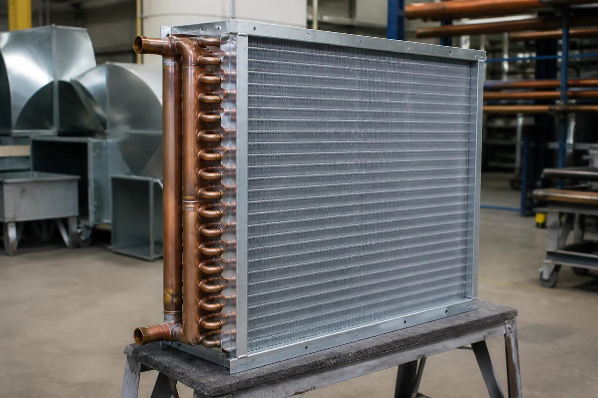
Technical details and manufacturing context for Heating/Cooling Coils
| Parameter | Typical range | Notes & selection driver |
|---|---|---|
| Nominal Diameter | DN15–DN300 mm | Common range for coil connectionsISO 6708 |
| Heat Transfer Area | 0.5–50 m² | Depends on coil rows and fin spacing |
| Operating Temperature | -40–150 °C | For water/glycol; steam up to 200°C |
| Test Pressure | 1.5–2.4 MPa | 1.5× operating pressure |
| Air Pressure Drop | 50–250 Pa | At face velocity 2–3 m/s |
| Water Pressure Drop | 10–80 kPa | At water velocity 0.6–1.5 m/s |
| Face Velocity | 1.5–3.5 m/s | Higher velocity increases pressure drop |
| Tube Material | Cu, CuNi, SS304, SS316 | Copper standard; SS for corrosiveASTM B75, A312 |
| Fin Material | Al, Cu, SS304, SS316 | Aluminum standard; SS for corrosiveASTM B209, A240 |
| Fin Spacing | 1.5–6.0 mm | Tighter spacing increases efficiency |
| Number of Rows | 1–8 | More rows increase capacity and drop |
| Weight | 10–500 kg | Depends on size and material |
Ranges are indicative industry figures for RFQ preparation, not a supplier commitment. Confirm every value and standard with the legal manufacturer before ordering.
| pressure: | Up to 2.5 MPa (25 bar) |
| flow rate: | 0.5 to 10 m/s air velocity |
| temperature: | -40°C to 200°C |
| slurry concentration: | Not applicable (clean fluids only) |
Indicative industry ranges for design and RFQ preparation. Confirm the exact figures and applicable standard with the manufacturer before specifying.
Quoted from the published standard.
A practical evidence checklist for RFQ preparation and supplier evaluation.
Compare the published product scope and source details, then include your specifications and quantity in an enquiry.
Manufacturer profiles associated with Heating/Cooling Coils.
Explore company information and manufacturing capabilities, then discuss the scope of your project with a relevant supplier.
Ask for use case, specification boundaries, supplier type, and RFQ preparation information for this product.
Common tube materials include copper, copper-nickel, and stainless steel (SS304, SS316). Fin materials are typically aluminum, copper, or stainless steel. Material selection depends on the application and corrosion requirements.
The typical operating pressure range is 1.0 to 1.6 MPa, with a test pressure of 1.5 to 2.4 MPa. These values are reference ranges and must be confirmed for the specific coil model.
Tighter fin spacing increases heat transfer efficiency but also increases air pressure drop. Fin spacing typically ranges from 1.5 to 6.0 mm, and the optimal spacing depends on the application and allowable pressure drop.
Relevant standards include ISO 6708 for nominal diameter, and ASTM B75, A312, B209, A240 for tube and fin materials. These are procurement references; verify compliance with the supplier.
This component is essential for the following industrial systems and equipment:
Editorial classification, named public sources where available, and source-reviewed manufacturer records.
Compare manufacturer profiles with relevant product and process capability.