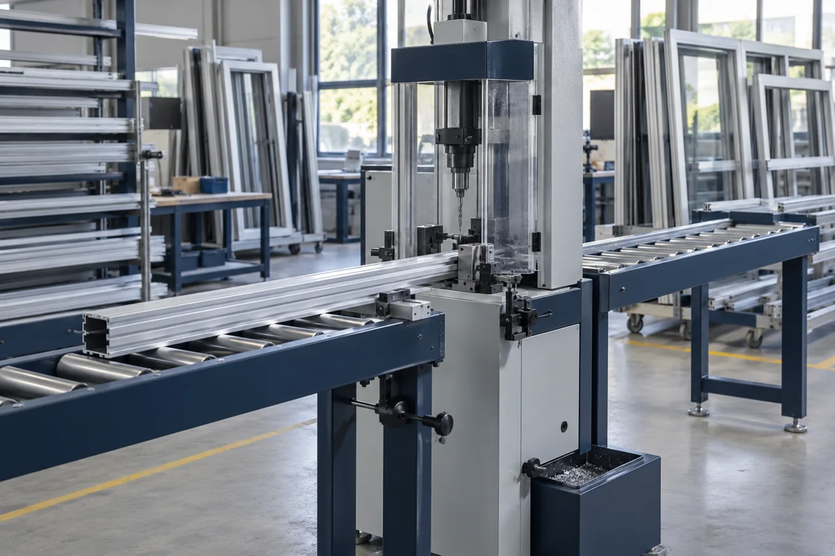
For a shutter or window extrusion, the hole pattern must fit the profile’s walls and cavities. Compare DEMAC’s two published machines, check what the speed and feed labels actually mean, and specify how the drill enters and leaves each wall. The machine catalogue and the cutting-tool guidance answer different parts of this decision.
CNFX editorial research · Sources checked October 12, 2026 · 4 sources
The SD-300 description names servo-controlled profile feeding and a power head with a multi-drilling-head adapter. It does not publish maximum stock length, feed positioning accuracy or the transmission between motor and tool. “Max. auto feeding 200mm” does not establish whether 200 mm means a stroke, programmed increment or pitch range; “No limited” is not evidence of unlimited working capacity. Ask for a drawing of the supported stock and a hole-pattern trial [1].
02
Follow the profile through the hole-making assembly
DEMAC describes CNC-controlled feeding, a servo feed and a power head with a multi-drill adapter. Follow those functions through the machine, then identify the delivered tools and auxiliaries. This is a functional assembly reference; materials, quantities and replacement-part identities require the machine supplier’s drawings [1].
Assembly role
What is established—and what the quotation must identify
CNC controller and feed command
The maker advertises CNC feeding. Confirm the control model, hole-pattern storage and whether profile positioning and drilling penetration feeds are independently programmable. No controller brand or cabinet material is published [1].
Servo profile feed and stock support
The description says a servo feeds the profile and feeding speed can be adjusted. Specify stock length, supported cross-section and clamping locations on a layout; the catalogue does not establish X/Y machining axes, linear-guide grade or positioning tolerance [1].
Power head / spindle drive
The head rotates the cutting tool; the table gives motor rpm and a power label. Confirm spindle output speed, holder and delivered drill arrangement. Spindle and bearing materials are not specified in the reviewed catalogue [1].
Multi-drill adapter and tooling
DEMAC describes single or multiple holes using an adapter. Obtain the delivered spindle count, spacing and approved drill/holder set. An adapter is not an automatic tool magazine; no magazine, tool-change cycle or ATC option is established by this page [1].
Coolant and chip-management equipment
Sandvik’s aluminium guide discusses adhesion, burrs and chip evacuation. DEMAC’s general discussion of newer machines with coolant does not establish an SD-300 mist system, through-spindle circuit or pump pressure. Identify what is actually supplied and how cavity chips are removed [2][1].
Require the delivered controller, spindle/adapter, feed drive and guide, coolant and tool-handling list. Workholding must be agreed for the actual thin-wall profile; neither source gives a clamping force or a permissible wall deformation.
03
Calculate cutting speed only after confirming tool rpm
Sandvik’s aluminium-alloy note recommends low feed and high speed for chip formation, with coating choice depending on the substrate, and emulsion or mist coolant at high pressure. It gives no numeric speed, feed or coolant-pressure setting for this DEMAC machine. The adjacent “up to 70 bar” recommendation belongs to titanium and heat-resistant alloys, not this aluminium paragraph [2].
Tool diameter
If the tool turns at 1400 rpm
If the tool turns at 2840 rpm
3 mm
13 m/min
27 m/min
5 mm
22 m/min
45 m/min
7 mm
31 m/min
62 m/min
Calculated examples, rounded to the nearest m/min: cutting speed = π × tool diameter in mm × actual tool rpm ÷ 1000. The six numbers above retain the original arithmetic, but DEMAC labels 1400/2840 rpm as motor speed. They are not verified SD-300 cutting speeds until the transmission ratio and actual tool speed are confirmed. Nor is the catalogue’s 3–7 mm router-bit label proof of drill capacity. Compare the approved tool’s own speed/feed guidance for the alloy, wall geometry and coolant arrangement [1][2].
04
Specify the hole pattern and the delivered machine
DEMAC’s short comparison table supplies only some of the data needed for an enquiry. The hollow extrusion, hole pattern and agreed delivery determine what goes in the following fields.
Field / unit
Published evidence or information to request
Spindle speed · rpm
Confirm actual tool rpm and adjustment range; 1400/2840 rpm are labelled motor speed, not spindle speed [1].
Drilling capacity · mm
Request approved drill types, diameters and penetration through your wall arrangement. The 3–7 mm router-bit entry is not a stated maximum drilling capacity [1].
Positioning accuracy · mm
Specify hole centres and accumulated pitch tolerance over the stock length, with measurement conditions. The SD-300 page publishes no numerical positioning accuracy [1].
Table size · mm
Request support/clamp layout and profile envelope. Machine dimensions do not establish usable table size or maximum stock length [1].
Spindle power · kW
The table labels 1.1 kW simply as power. Ask whether this is motor rating, spindle output or another electrical basis; do not treat it as total installed load [1].
Number of spindles · count
Distinguish one power head from an adapter’s multiple drilling outputs. Confirm what is delivered and what hole spacing can be set [1].
Rapid traverse · m/min
Request positioning speed, drilling penetration feed and cycle-time basis separately. No X/Y rapid-rate value is published for these profile machines [1].
Tool interface
Obtain the actual holder/collet and approved tool dimensions. A catalogue description of profile drilling does not prove a machining-centre taper or ATC capability [1].
Control system
Ask for the control model, programme limits and demonstrated entry/exit feed control; the page advertises CNC feeding without a controller specification [1].
Machine weight · kg
Request operating and shipping masses, lifting points and foundation requirements. No machine mass is stated in the reviewed table [1].
Power supply
Both model rows say 380 V, 50 Hz. Other voltage availability and phase/current/protection requirements need written confirmation [1].
Air pressure · MPa
Ask whether pneumatic clamps or chip-clearing devices are fitted and request their pressure/flow requirements. The reviewed catalogue does not establish either system on this delivery [1].
Coolant / pressure · MPa
Specify the supplied cooling method and fluid/flow/pressure requirements. Neither optional through-spindle coolant nor a numerical pump pressure is established for these models [1][2].
For upkeep, request the model’s lubrication, guide/drive inspection, clamping and chip-clearing instructions, service limits and safe isolation procedure. The reviewed sources do not supply maintenance intervals or authorize hands-on work around a rotating tool. Include replacement drill/holder and adapter identifiers in the service handover.
05
Drill hollow, curved and inclined profile walls
Sandvik separates solid-carbide, exchangeable-tip and indexable-drill guidance. The conditions here are from its solid-carbide section; they are not universal rules for every router bit, drill head or thermal-drilling process. Hollow profiles need the entry, cavity crossing and exit sequence shown on the section drawing [3].
Worked example
For a 5 mm solid-carbide drill, the guide’s geometric tests give a convex radius greater than 20 mm or a concave radius greater than 75 mm, with perpendicular entry in both cases. These are 4×D and 15×D calculations, not permission for every curved profile: inclination, asymmetry, tool type and the exit wall still need review [3].
Ask for feed control at entry and exit
Give the supplier the section drawing and the sequence through each wall, then ask it to demonstrate the required drilling feed changes on the actual control. CNC profile positioning does not itself prove independently programmed entry/exit drilling feeds [1][3].
Irregular entry and exit
Reduce feed to 25% of the recommended feed until the full diameter is cutting, following the solid-carbide guide. Small drills are particularly susceptible to deflection, wandering or breakage; this is a proportion of an already established tool feed, not a standalone setting [3].
Convex face
Radius greater than 4×D and the hole perpendicular to the surface radius; use 50–100% of recommended feed until fully engaged. Milling a flat is an alternative [3].
Concave face
Radius greater than 15×D and hole perpendicular to the surface radius; use 30% feed until fully engaged. Milling a flat is an alternative [3].
Inclined face
Up to 10° inclination: 30% feed until full engagement. Above 10°, the guide does not recommend solid-carbide drilling of that inclined surface; consider preparing a flat [3].
Crossing another hole
Drill the larger hole first. The solid-carbide guidance specifies 25% feed when crossing at depths below 12×D; do not extend that exact rule to every depth or drill type [3].
Pre-drilled or asymmetrical curved entry
The guide does not recommend drilling into pre-drilled holes because of cutting-edge chipping risk. It says solid-carbide drills cannot be used on asymmetrically curved surfaces where the tip may not contact first. A pilot hole is therefore not an automatic solution to every difficult profile wall [3].
06
Know the material you are drilling
Hydro describes 6063 as "one of the more popular alloys for aluminium extrusion", alloyed with magnesium and silicon, with better surface finish than structural alloys and good extrudability [4].
Check claims about silicon
DEMAC makes a blanket “more than eleven percent silicon” statement about aluminium. Hydro’s reviewed 6063 article describes a magnesium-silicon extrusion alloy but gives no composition percentages. That article cannot validate DEMAC’s number, and this page does not substitute an unverified chemical limit. Identify the stock by its alloy/temper certificate and use tooling guidance for that material [1][4].
Adhesion and burrs are the usual problems
Sandvik names burr formation, chip evacuation and adhesion as the main issues when drilling aluminium alloys [2]. Ask for the burr limit at hole exits and how chips are removed from inside hollow profiles.
Typical use
Window systems, door frames and facade profiles; it anodizes well [4]
Tempers
"T5 and T6 are the most common for extruded profiles"; T66 for more strength [4]
Structural loads
For profiles carrying significant structural stress, 6082 is likely more appropriate [4]
07
Copy this RFQ and fill in the brackets
Paste it into your enquiry below or into an email to a maker, then replace every bracket.
Product: aluminium extrusion hole-drilling station, quantity [ ]
Stock: alloy/temper certificate [ ], section drawing, length [ ], wall thickness [ ]
Hole pattern: diameters/pitch/tolerances [ ], one/both walls, curved entry and exits [ ]
Tooling: approved drill/holder, actual tool rpm/feed, spindle count and adapter spacing [ ]
Positioning: supported stock and clamps, feed stroke/pitch meaning, accuracy test [ ]
Drilling control: demonstrated entry/crossing/exit feed changes on our section [ ]
Quality trial: sample quantity [ ], measured pitch and burr limits, cavity chip inspection [ ]
Utilities: electrical rating/basis, fitted air/coolant equipment and requirements [ ]
Delivered scope: support benches, guarding, tools, adapter, coolant and exclusions [ ]
Handover: control files, assembly/spare identifiers, service and isolation instructions [ ]
Destination/date [ ], trial and delivery acceptance documents [ ]
The company below publishes the reviewed SD-300/LZD1-17 page. The public catalogue confirms advertised product scope; it is not company-claim verification or a witnessed performance test.
DEMAC
Jinan, Shandong (published address), CN
DEMAC advertises shutter/window/door/curtain-wall profile drilling, comparing a single-head LZD1-17 with an automatic single-head SD-300. Its SD-300 description names servo profile feeding and a multi-drill adapter. Motor rpm, a router-bit diameter and an ambiguous 200 mm feed label do not establish tool speed, drilling capacity or pitch tolerance. Send the section and hole pattern and request a witnessed trial and delivered-equipment list.
Explore company information and manufacturing capabilities, then discuss the scope of your project with a relevant supplier.
Share this page
Compiled and source-reviewed by the CNFX editorial team.
Each manufacturer above links to the page on that company's own website where the product is listed, with the date we checked it. How we source and review
· Page last updated 13 October 2026
Buyer questions
Is 2840 rpm fast enough to drill aluminium?
At an actual tool speed of 2840 rpm, a 5 mm diameter gives about 45 m/min by πDn/1000. DEMAC labels that number motor speed; confirm the transmission and actual tool speed before using the calculation. Compare with the selected drill’s own cutting recommendation rather than accepting one rpm for all aluminium holes. [1][2]
How do I drill holes on a curved profile face?
The solid-carbide guidance requires perpendicular entry with radius greater than 4×D on convex or 15×D on concave faces, and reduced feed. It treats inclined and asymmetrically curved surfaces separately. Identify the tool and complete wall geometry; a radius alone is insufficient. [3]
Which aluminium alloy are window profiles made of?
Hydro lists window systems, door frames and facade profiles among 6063 applications and says "T5 and T6 are the most common for extruded profiles". That does not identify every window profile: provide the actual alloy/temper certificate rather than assuming 6063 from appearance. [4]
How do I reduce burrs where holes cross?
Sandvik’s solid-carbide section recommends drilling the larger hole first; its 25% crossing-feed instruction is scoped to depths below 12×D. Tool type, crossing depth and the recommended base feed must be known before applying it. [3]
Sources and what still needs a direct check
Sources checked 2026-10-12. Standards bodies and regulations define the requirements; manufacturer pages show published ranges for those models only. CNFX does not certify products or suppliers.