Editorial Technical Reference

Gas Distribution System

This page explains how Gas Distribution System is classified within Chemical Manufacturing. Technical values and manufacturer relationships are research references; confirm the current specification and supplier evidence for each order.

Technical Definition & Core Assembly

A system within a high-pressure ammonia synthesis reactor that precisely controls and distributes reactant gases to the catalyst bed.
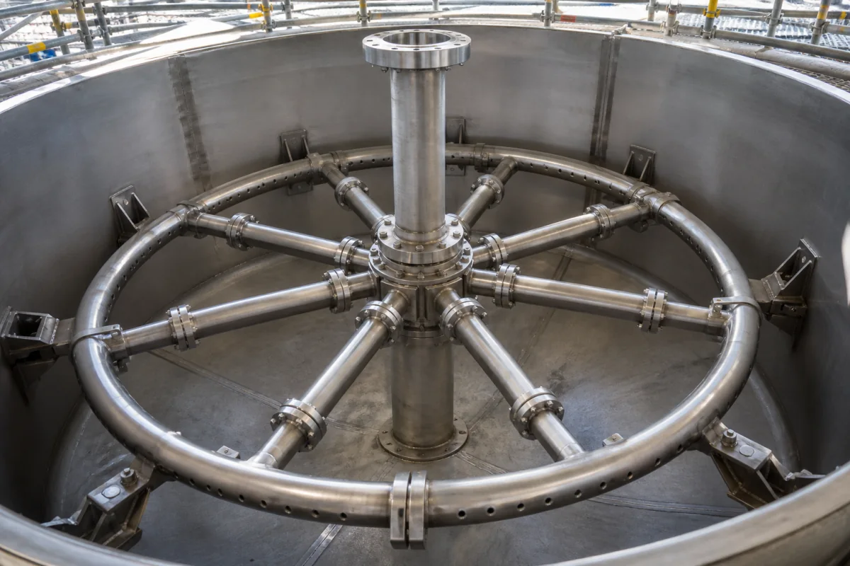
Representative product image. Confirm appearance and specifications with the manufacturer.

Product Specifications

Technical details and manufacturing context for Gas Distribution System

Definition
The Gas Distribution System is a critical component of a High-Pressure Ammonia Synthesis Reactor responsible for the uniform introduction and distribution of the nitrogen-hydrogen synthesis gas mixture (typically at 150-300 bar) across the entire cross-section of the catalyst bed. It ensures optimal contact between the reactants and the catalyst, preventing channeling and hot spots, which is essential for maximizing reaction efficiency, yield, and operational safety. The system typically comprises a sparger, distributor plate, or a network of nozzles, engineered to create a balanced pressure profile above the catalyst bed, forcing the gas to flow evenly through the bed material. This design facilitates the catalytic reaction (N₂ + 3H₂ ⇌ 2NH₃) by ensuring that all catalyst particles are exposed to the reactant gas. The system is constructed from high-grade stainless steel (e.g., 316L, 321) and alloy steel for high-pressure and high-temperature sections, providing corrosion resistance in the ammonia environment. Key parameters include an operating pressure of 1.0–1.6 MPa, design temperature of 350–550°C, gas flow rate of 5000–20000 Nm³/h, pressure drop of 0.05–0.15 MPa, distribution uniformity of ±5%, material grade 316L (ASTM A312), connection size DN50–DN300 (DIN EN 1092-1), leakage rate ≤0.01% (ISO 15848-1), weight 500–2000 kg, and operating humidity ≤85% RH. These values are directory reference ranges and must be confirmed for the specific model and application with the legal manufacturer or supplier. The system is designed to meet safety and environmental compliance standards, and its performance directly impacts reactor capacity and energy consumption. Proper selection requires consideration of reactor inlet piping, support structure, and operating conditions. Regular maintenance and monitoring of pressure drop and distribution uniformity are essential to detect wear, fouling, or blockage, which can lead to reduced efficiency or unsafe operation. Failure to maintain the system can result in channeling, hot spots, and reduced catalyst life, compromising overall plant safety and productivity.
Working Principle
High-pressure synthesis gas (N₂ + 3H₂) enters the system via an inlet manifold. The system, often comprising a sparger, distributor plate, or a network of nozzles, uses pressure differentials and engineered flow paths to disperse the gas uniformly. It creates a balanced pressure profile above the catalyst bed, forcing the gas to flow evenly through the bed material to facilitate the catalytic reaction (N₂ + 3H₂ ⇌ 2NH₃).
Common Materials
High-grade stainless steel (e.g., 316L, 321), Alloy steel (for high-pressure/temperature sections)
Technical Parameters
ParameterTypical rangeNotes & selection driver
Design Temperature350–550 °CAbove 550°C material creep becomes critical
Gas Flow Rate5000–20000 Nm³/hDetermines reactor capacity
Pressure Drop0.05–0.15 MPaAffects energy consumption
Distribution Uniformity±5 %Ensures catalyst utilization
Material Grade316LCorrosion resistance in ammonia environmentASTM A312
Connection SizeDN50–DN300 mmMatches reactor inlet pipingDIN EN 1092-1
Leakage Rate≤0.01 %Safety and environmental complianceISO 15848-1
Weight500–2000 kgAffects installation and support structure
Operating Humidity≤85 %RHPrevents condensation and corrosion

Ranges are indicative industry figures for RFQ preparation, not a supplier commitment. Confirm every value and standard with the legal manufacturer before ordering.

Components / BOM
  • Inlet Manifold/Header
    Receives high-pressure feed gas from the reactor inlet and distributes it to the primary distribution network.
    Material: Forged alloy steel or stainless steel
  • Distribution Plate/Sparger
    A perforated plate or pipe assembly with precisely sized holes/nozzles that creates the final uniform gas flow profile into the catalyst bed.
    Material: Stainless steel
  • Support Grid/Structure Part
    Provides mechanical support for the distribution plate and catalyst bed, often integrated with the distributor.
    Material: Alloy steel

Applied To / Applications

This component is essential for the following industrial systems and equipment:

Industrial Ecosystem & Supply Chain Structure

Complementary Systems
Downstream Applications
Specialized Tooling

Application Fit & Sizing Matrix

Operational Limits
pressure: 100-300 bar (high-pressure reactor conditions)
flow rate: 10-1000 Nm³/h (scaled to reactor capacity)
temperature: 200-500°C (typical ammonia synthesis operating range)
slurry concentration: Not applicable (gas-phase system)
Media Compatibility
✓ Ammonia synthesis gas (N2/H2 mixture) ✓ High-pressure hydrogen ✓ Inert gas purges (e.g., nitrogen)
Unsuitable: Oxygen-containing streams (risk of oxidation/explosion)
Sizing Data Required
  • Reactor design pressure (bar)
  • Total gas flow rate (Nm³/h)
  • Catalyst bed configuration (dimensions/distribution pattern)

Reliability & Engineering Risk Analysis

Failure Mode & Root Cause
Corrosion-induced leakage
Cause: Electrochemical degradation of pipeline material due to moisture, soil chemistry, or stray currents, leading to wall thinning and eventual breach.
Mechanical fatigue cracking
Cause: Cyclic stress from pressure fluctuations, ground movement, or vibration, initiating cracks at weld joints or material imperfections that propagate over time.
Maintenance Indicators
  • Audible hissing or whistling near pipeline joints or valves indicating gas escape
  • Visual dead vegetation or bubbling in wet soil along pipeline route suggesting subsurface leakage
Engineering Tips
  • Implement cathodic protection systems with regular potential monitoring to prevent corrosion, supplemented by periodic inline inspection using smart pigs to detect wall thickness anomalies.
  • Install pressure regulation and surge suppression devices at strategic points to minimize cyclic stress, combined with geotechnical stabilization in areas prone to ground movement.

Indicative industry ranges for design and RFQ preparation. Confirm the exact figures and applicable standard with the manufacturer before specifying.

Compliance & Manufacturing Standards

Applicable Standards
ISO 13623:2017 - Petroleum and natural gas industries - Pipeline transportation systems ASME B31.8 - Gas Transmission and Distribution Piping Systems EN 12007 - Gas infrastructure - Pipelines for maximum operating pressure up to and including 16 bar

Quoted from the published standard.

Manufacturing Precision
  • Pipe Wall Thickness: +/-10% of nominal thickness
  • Weld Reinforcement Height: Maximum 3mm above base metal surface
Quality Inspection
  • Hydrostatic Pressure Test - 1.5 times maximum operating pressure for 24 hours
  • Ultrasonic Testing (UT) for weld integrity and material thickness verification

Manufacturers of Gas Distribution System

Manufacturer profiles associated with Gas Distribution System.

Sourcing Gas Distribution System from China?
Tell us your specification and target quantity — we will match it against manufacturer records and come back with the factories that fit.
Request manufacturers We manufacture this

Manufacturer listings support early research and capability understanding. They are not certification, ranking, or transaction guarantees.

Technical documentation
Request current drawings, revision history, and a signed specification sheet.
Manufacturing capability
Verify equipment lists, process limits, capacity, and representative production evidence.
Inspection readiness
Confirm test methods, calibrated equipment, sampling plans, and traceable reports.
Supplier transparency
Check the legal entity, factory address, ownership, certifications, and direct contacts.

CNFX does not score or rank suppliers. Buyers must verify all claims and documents with the legal manufacturer before ordering.

Supply Chain Compatible Machinery & Devices

Continuous Flow Reactor System

A modular, automated chemical processing system designed for continuous flow synthesis of chemical products.

Explore Specs →
Automated Batch Crystallization System

Automated system for controlled crystallization of chemical compounds in batch processes.

Explore Specs →
Automated pH Monitoring and Dosing System

Automated system for continuous pH monitoring and chemical dosing in process streams.

Explore Specs →
Automated Powder Dispensing and Blending System

Automated system for precise dispensing and homogeneous blending of powdered chemicals.

Explore Specs →

Frequently Asked Questions

What is the primary function of the Gas Distribution System?

The primary function is to uniformly distribute the nitrogen-hydrogen synthesis gas mixture across the entire cross-section of the catalyst bed in a high-pressure ammonia synthesis reactor. This ensures optimal contact between reactants and catalyst, preventing channeling and hot spots, which is essential for maximizing reaction efficiency and safety.

What are the typical operating pressure and temperature ranges?

According to directory reference data, the operating pressure is typically 1.0–1.6 MPa, and the design temperature ranges from 350–550°C. These values must be confirmed for the specific model and application with the legal manufacturer or supplier.

Which materials are commonly used for construction?

The system is typically constructed from high-grade stainless steel (e.g., 316L, 321) and alloy steel for high-pressure and high-temperature sections. The material grade 316L is listed per ASTM A312, providing corrosion resistance in ammonia environments.

How does the system affect reactor performance?

The system ensures uniform gas distribution, which directly impacts reaction efficiency, yield, and operational safety. Parameters such as pressure drop (0.05–0.15 MPa) and distribution uniformity (±5%) influence energy consumption and catalyst utilization. Proper maintenance is crucial to avoid performance degradation.

Data Basis

Editorial classification, named public sources where available, and source-reviewed manufacturer records.

Preliminary Technical Classification
This page supports structured research, RFQ preparation, and supplier evaluation. It does not replace buyer-led supplier qualification, standards review, or technical approval.
Buyer enquiry

Request manufacturing insight for Gas Distribution System

Ask for use case, specification boundaries, supplier type, and RFQ preparation information for this product.

Where it goes
Straight to the CNFX editorial desk, and to the manufacturer if this product is linked to a claimed profile. Nothing is broadcast to a supplier list.
Your details stay here
We do not sell or rent enquiry data, and we do not add you to a mailing list. Used only to answer this request.
No commission, no middleman
CNFX is a directory. We take no cut of any order and never negotiate on a supplier's behalf.
What we don't claim
A listing is not an endorsement. Qualify every supplier and verify every figure yourself before ordering.

Your business information is used only to process this request.

Thank you! Your message has been sent. We'll respond within 1–3 business days.
Sorry, we couldn't send your message. Please try again, or email us at contact@cnfx.com.

Need to Manufacture Gas Distribution System?

Compare manufacturer profiles with relevant product and process capability.

Previous Product
Twin-Screw Polymer Compounding Extruder
Last Product
Get QuotesChat