Editorial Technical Reference

Continuous Flow Reactor System

This page explains how Continuous Flow Reactor System is classified within Chemical Manufacturing. Technical values and manufacturer relationships are research references; confirm the current specification and supplier evidence for each order.

Technical Definition & Core Assembly

A modular, automated chemical processing system designed for continuous flow synthesis of chemical products.

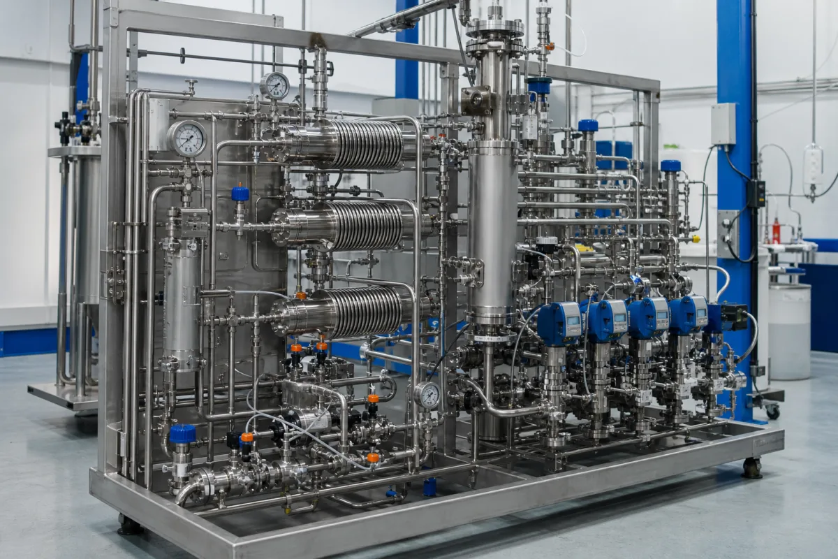
Continuous Flow Reactor System in a manufacturing environment
Representative product image. Confirm appearance and specifications with the manufacturer.

Product Specifications

Technical details and manufacturing context for Continuous Flow Reactor System

Definition
A modular, automated chemical processing system designed for continuous flow synthesis of chemical products. It integrates reaction, mixing, heating/cooling, and separation modules in a closed-loop configuration to enable safer, more efficient, and scalable production compared to traditional batch reactors. The system is particularly suited for hazardous reactions, high-value intermediates, and processes requiring precise temperature and residence time control. It supports real-time monitoring and process analytical technology (PAT) integration for quality assurance. The system is constructed with materials such as 316L stainless steel, PTFE (Teflon), borosilicate glass, silicone gaskets, and ceramic heating elements, ensuring compatibility with a range of chemical families including acids and solvents. Key parameters include a flow rate range of 0.5–50 mL/min, operating temperature from -40 to 200 °C, pressure rating of 1.0–1.6 bar, reactor volume of 0.1–10 mL, heat transfer area of 0.1–2.0 m², residence time of 0.5–120 min, temperature control accuracy of ±0.5 °C, pressure control accuracy of ±0.01 MPa, electrical supply of 220–380 V AC (50/60 Hz, 3-phase), power consumption of 2–15 kW, ingress protection of IP54–IP65 (IEC 60529), weight of 200–1500 kg, and dimensions of 1200×800×1600 mm. These values are reference ranges and must be verified for the specific model and application with the legal manufacturer or supplier. The system is skid-mounted with a compact design, suitable for laboratory to pilot-scale production. It is essential to confirm material compatibility, standards compliance, and installation requirements before procurement.
Working Principle
Chemical reactants are continuously pumped through a series of interconnected modules (reactors, mixers, heat exchangers) where reactions occur under controlled conditions, with products continuously collected downstream. The system maintains precise temperature and pressure, and residence time is adjusted via flow rate and reactor volume. Real-time monitoring and PAT integration allow for quality assurance and process optimization.
Common Materials
316L stainless steel, PTFE (Teflon), borosilicate glass, silicone gaskets, ceramic heating elements
Technical Parameters
ParameterTypical rangeNotes & selection driver
Flow RateRequired0.5–50 mL/minMaximum continuous flow capacity
Temperature RangeRequired-40–200 °COperating temperature range (min to max)
Pressure RatingRequired1.0–1.6 barMaximum allowable working pressure
Reactor Volume0.1–10 mLTotal internal reactor volume
Material CompatibilityRequired316L, Hastelloy C-276, PTFE noneCompatible chemical families (e.g., acids, solvents)ASTM A240
Heat Transfer Area0.1–2.0 Determines heating/cooling efficiency
Residence Time0.5–120 minAdjustable via flow rate and volume
Temperature Control Accuracy±0.5 °CEnsures reaction consistency
Pressure Control Accuracy±0.01 MPaCritical for gas-liquid reactions
Electrical Supply220–380 V AC50/60 Hz, 3-phaseIEC 60038
Power Consumption2–15 kWDepends on heating/cooling demand
Ingress ProtectionIP54–IP65Higher IP for washdown areasIEC 60529
Weight200–1500 kgDepends on configuration
Dimensions (L×W×H)1200×800×1600 mmSkid-mounted, compact design

Ranges are indicative industry figures for RFQ preparation, not a supplier commitment. Confirm every value and standard with the legal manufacturer before ordering.

Components / BOM
  • Feed Pump Module
    Precise metering and delivery of reactants
    Material: 316L stainless steel/PTFE
  • Reactor Core
    Primary reaction chamber with temperature control
    Material: 316L stainless steel/borosilicate glass
  • Heat Exchanger
    Heating or cooling of reaction stream
    Material: 316L stainless steel
  • Back Pressure Regulator Part
    Maintains system pressure and controls flow
    Material: 316L stainless steel
  • Control System
    Automated process control and monitoring
    Material: Electronics enclosure (ABS/steel)
  • In-line Analyzer Port Optional Part
    Integration point for PAT sensors (e.g., IR, UV)
    Material: 316L stainless steel

Industry Taxonomies & Aliases

Commonly used trade names and technical identifiers for Continuous Flow Reactor System.

Industrial Ecosystem & Supply Chain Structure

Complementary Systems
Downstream Applications
Specialized Tooling

Application Fit & Sizing Matrix

Operational Limits
pressure: Up to 100 bar
flow rate: 0.1-100 mL/min per channel
temperature: -20°C to 250°C
slurry concentration: Up to 30% solids by volume
Media Compatibility
✓ Organic solvents (e.g., DMF, THF, acetone) ✓ Aqueous acidic/basic solutions (pH 2-12) ✓ Gaseous reactants (e.g., H2, CO2, O2)
Unsuitable: Hydrofluoric acid or highly concentrated halogenated media (due to corrosion risk with standard wetted materials)
Sizing Data Required
  • Required production rate (kg/day or L/day)
  • Reaction residence time (seconds to minutes)
  • Number of parallel reactions or stages needed

Reliability & Engineering Risk Analysis

Failure Mode & Root Cause
Corrosion-induced pitting
Cause: Chemical attack from aggressive reactants or byproducts, especially at high temperatures and pressures, leading to localized material degradation and potential leaks.
Thermal fatigue cracking
Cause: Repeated thermal cycling during startup, shutdown, or process variations causing stress concentrations at weld joints or nozzle connections, resulting in crack propagation.
Maintenance Indicators
  • Unusual vibration or audible knocking from the reactor vessel, indicating potential internal component failure or flow disruption.
  • Visible discoloration, bulging, or weeping at weld seams or connections, suggesting material degradation or imminent leak.
Engineering Tips
  • Implement real-time corrosion monitoring with ultrasonic thickness testing and inline pH/conductivity sensors to detect early wall thinning and adjust process parameters proactively.
  • Optimize thermal cycling protocols by using controlled heating/cooling rates and maintaining minimum temperature thresholds during idle periods to reduce thermal stress accumulation.

Indicative industry ranges for design and RFQ preparation. Confirm the exact figures and applicable standard with the manufacturer before specifying.

Compliance & Manufacturing Standards

Applicable Standards
ASME BPE-2022 - Bioprocessing Equipment CE Marking - Machinery Directive 2006/42/EC

Quoted from the published standard.

Manufacturing Precision
  • Tube Bore Diameter: +/-0.05mm
  • Surface Finish (Ra): 0.4μm maximum
Quality Inspection
  • Pressure Test (Hydrostatic/Pneumatic) to 1.5x design pressure
  • Material Traceability Verification (Mill Certificates)

Manufacturers of Continuous Flow Reactor System

Manufacturer profiles associated with Continuous Flow Reactor System.

Sourcing Continuous Flow Reactor System from China?
Tell us your specification and target quantity — we will match it against manufacturer records and come back with the factories that fit.
Request manufacturers We manufacture this

Manufacturer listings support early research and capability understanding. They are not certification, ranking, or transaction guarantees.

Share this page
Technical documentation
Request current drawings, revision history, and a signed specification sheet.
Manufacturing capability
Verify equipment lists, process limits, capacity, and representative production evidence.
Inspection readiness
Confirm test methods, calibrated equipment, sampling plans, and traceable reports.
Supplier transparency
Check the legal entity, factory address, ownership, certifications, and direct contacts.

CNFX does not score or rank suppliers. Buyers must verify all claims and documents with the legal manufacturer before ordering.

Supply Chain Commonly Integrated Components

Dust Collection Unit

A filtration system component that captures and contains airborne particulate matter generated during catalyst handling operations

Explore Specs →
Inert Gas Purge System

A safety system that uses inert gases to displace oxygen and flammable vapors from catalyst handling equipment to prevent combustion and oxidation during loading/unloading operations.

Explore Specs →
Drum Conveyor

A mechanical handling device designed to transport chemical drums through an automated filling and sealing system.

Explore Specs →
Process Pump

A mechanical device designed to move chemical fluids through filtration and separation processes by creating flow and pressure.

Explore Specs →

Frequently Asked Questions

What materials are used in the system?

The system is constructed with 316L stainless steel, PTFE (Teflon), borosilicate glass, silicone gaskets, and ceramic heating elements. These materials provide compatibility with various chemical families, but specific compatibility must be verified for your process.

What is the operating temperature range?

The system operates within a temperature range of -40 to 200 °C. The temperature control accuracy is ±0.5 °C, ensuring precise reaction conditions. Confirm the range for your specific model.

Can the system handle hazardous reactions?

Yes, the closed-loop design and precise control make it suitable for hazardous reactions. However, you must verify that the system's pressure rating, materials, and safety features meet your specific requirements.

What is the flow rate capacity?

The maximum continuous flow capacity is 0.5–50 mL/min. The actual flow rate depends on the reactor volume and residence time settings. Verify the capacity for your intended application.

Data Basis

Editorial classification, named public sources where available, and source-reviewed manufacturer records.

Preliminary Technical Classification
This page supports structured research, RFQ preparation, and supplier evaluation. It does not replace buyer-led supplier qualification, standards review, or technical approval.
Buyer enquiry

Request manufacturing insight for Continuous Flow Reactor System

Ask for use case, specification boundaries, supplier type, and RFQ preparation information for this product.

Where it goes
Straight to the CNFX editorial desk, and to the manufacturer if this product is linked to a claimed profile. Nothing is broadcast to a supplier list.
Your details stay here
We do not sell or rent enquiry data, and we do not add you to a mailing list. Used only to answer this request.
No commission, no middleman
CNFX is a directory. We take no cut of any order and never negotiate on a supplier's behalf.
What we don't claim
A listing is not an endorsement. Qualify every supplier and verify every figure yourself before ordering.

Your business information is used only to process this request.

Thank you! Your message has been sent. We'll respond within 1–3 business days.
Sorry, we couldn't send your message. Please try again, or email us at [email protected].

Need to Manufacture Continuous Flow Reactor System?

Compare manufacturer profiles with relevant product and process capability.

Previous Product
Continuous Flow Pharmaceutical Reactor
Next Product
Crystallization Vessel
Get QuotesChat