Editorial Technical Reference

Inter-stage Transfer Pump/Piping

This page explains how Inter-stage Transfer Pump/Piping is classified within Chemical Manufacturing. Technical values and manufacturer relationships are research references; confirm the current specification and supplier evidence for each order.

Technical Definition & Core Assembly

A system that transfers concentrated liquid between successive evaporation stages in a multi-stage vacuum evaporator train.
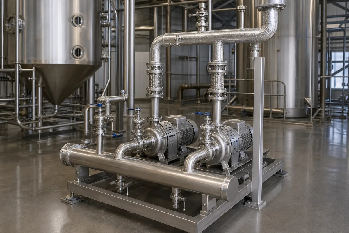
Representative product image. Confirm appearance and specifications with the manufacturer.

Product Specifications

Technical details and manufacturing context for Inter-stage Transfer Pump/Piping

Definition
The inter-stage transfer pump/piping is a critical component within a multi-stage vacuum evaporator train. It facilitates the movement of partially concentrated liquid from one evaporation stage to the next, ensuring continuous flow through the system. By transferring the product under controlled conditions, often maintaining vacuum, it maintains process efficiency and enables further concentration in subsequent stages. The system typically comprises a pump, such as a centrifugal or positive displacement pump designed for viscous fluids and vacuum service, which creates the necessary pressure differential to move the liquid. The associated piping network, including valves and instrumentation, directs the flow from the discharge of one evaporator stage to the feed of the next. The design must accommodate the fluid's increasing viscosity and solids content as it progresses through the stages. Materials commonly specified include stainless steel (e.g., 316L), duplex stainless steel, and Hastelloy, chosen for corrosion resistance and mechanical strength. Key parameters to consider include flow rate (5–50 m³/h), head (20–80 m), operating pressure (1.0–1.6 MPa), operating temperature (-20–150°C), motor power (2.2–30 kW), voltage (380–690 V AC), ingress protection (IP54–IP65), pipe diameter (DN25–DN100), pipe wall thickness (2.0–6.0 mm), and weight (50–500 kg). These values are reference ranges and must be verified against the specific application and manufacturer data. Standards such as ISO 9906, EN 12516-1, IEC 60034-1, IEC 60038, IEC 60529, ASTM A240, and ISO 4200 are referenced for procurement and verification. Always confirm model-specific values and standards with the legal manufacturer or supplier.
Working Principle
The pump generates a pressure differential that overcomes the inter-stage pressure difference and friction losses in the piping, moving the concentrated liquid from one evaporator stage to the next. The piping network, with valves and instrumentation, ensures controlled flow and maintains vacuum integrity. The system is designed to handle increasing viscosity and solids content, with materials selected for corrosion resistance. Proper sizing of pump and piping is essential to maintain continuous operation and prevent cavitation or excessive wear.
Common Materials
Stainless Steel (e.g., 316L), Duplex Stainless Steel, Hastelloy
Technical Parameters
ParameterTypical rangeNotes & selection driver
Flow Rate5–50 m³/hSelect based on evaporation capacityISO 9906
Head20–80 mMust overcome inter-stage pressure differenceISO 9906
Operating Pressure1.0–1.6 MPa
Operating Temperature-20–150 °CAbove 150°C requires special gasket materialEN 12516-1
Motor Power2.2–30 kWMatch with pump duty pointIEC 60034-1
Voltage380–690 V ACThree-phase, 50/60 HzIEC 60038
Ingress ProtectionIP54–IP65IP65 for outdoor or washdown areasIEC 60529
Material316LCorrosion-resistant for concentrated liquidsASTM A240
Pipe DiameterDN25–DN100 mmMatch with pump connectionsISO 4200
Pipe Wall Thickness2.0–6.0 mmPressure rating and corrosion allowanceISO 4200
Weight50–500 kgIncluding pump and baseplate

Ranges are indicative industry figures for RFQ preparation, not a supplier commitment. Confirm every value and standard with the legal manufacturer before ordering.

Components / BOM
  • Transfer Pump
    Provides the motive force to move the viscous, concentrated liquid from one stage to the next.
    Material: Stainless Steel Casting/Impeller
  • Interconnecting Piping Part
    Conduit for fluid transfer, designed to minimize pressure drop and accommodate thermal expansion.
    Material: Stainless Steel Pipe
  • Isolation Valve
    Allows for maintenance isolation of the pump or piping section.
    Material: Stainless Steel
  • Flow Instrumentation
    Measures inter-stage flow and pressure so the transfer can be regulated and cavitation spotted.

Industry Taxonomies & Aliases

Commonly used trade names and technical identifiers for Inter-stage Transfer Pump/Piping.

Applied To / Applications

This component is essential for the following industrial systems and equipment:

Industrial Ecosystem & Supply Chain Structure

Complementary Systems
Downstream Applications
Specialized Tooling

Application Fit & Sizing Matrix

Operational Limits
pressure: Vacuum to 10 bar (g), typical operating 0.5-3 bar (g)
flow rate: 5-200 m³/h (typical), depends on evaporator capacity
other spec: NPSHr < 2 m, materials compatible with corrosive/concentrated liquids
temperature: 50-150°C (typical), up to 200°C with special seals
slurry concentration: Up to 60% solids by weight, viscosity < 5000 cP
Media Compatibility
✓ Concentrated sugar syrups in food processing ✓ Caustic solutions in chemical plants ✓ Brine concentrates in desalination
Unsuitable: Abrasive slurries with hard particles > 200 microns (causes excessive wear)
Sizing Data Required
  • Evaporator stage capacity (kg/h of concentrate)
  • Required differential pressure between stages (bar)
  • Fluid properties (viscosity, density, corrosivity)

Reliability & Engineering Risk Analysis

Failure Mode & Root Cause
Cavitation
Cause: Insufficient NPSH (Net Positive Suction Head) due to low suction pressure, high fluid temperature, or excessive pump speed, leading to vapor bubble formation and implosion that damages impeller surfaces.
Abrasive erosion
Cause: Presence of solid particles in the fluid stream causing progressive material loss on impeller vanes, casing walls, and wear rings, often accelerated by high velocities or improper material selection.
Maintenance Indicators
  • Excessive vibration or audible knocking sounds indicating cavitation or bearing wear
  • Visible leakage at mechanical seals or flange connections with pressure drop across the system
Engineering Tips
  • Implement routine NPSH monitoring and maintain suction pressure above vapor pressure through proper piping design and operational controls
  • Install particle filtration upstream and select hardened materials (e.g., tungsten carbide coatings) for wear-prone components based on particle analysis

Indicative industry ranges for design and RFQ preparation. Confirm the exact figures and applicable standard with the manufacturer before specifying.

Compliance & Manufacturing Standards

Applicable Standards
ISO 2858:2012 - End-suction centrifugal pumps (Designation, nominal duty point and dimensions) ANSI/ASME B73.1 - Specification for Horizontal End Suction Centrifugal Pumps for Chemical Process DIN EN 22858 - End-suction centrifugal pumps - Rating, performance and dimensions

Quoted from the published standard.

Manufacturing Precision
  • Impeller Diameter: +/-0.5mm
  • Shaft Runout: 0.025mm maximum
Quality Inspection
  • Hydrostatic Pressure Test (1.5x design pressure)
  • Dimensional Verification (Critical mating surfaces and alignment features)

Manufacturers of Inter-stage Transfer Pump/Piping

Manufacturer profiles associated with Inter-stage Transfer Pump/Piping.

Sourcing Inter-stage Transfer Pump/Piping from China?
Tell us your specification and target quantity — we will match it against manufacturer records and come back with the factories that fit.
Request manufacturers We manufacture this

Manufacturer listings support early research and capability understanding. They are not certification, ranking, or transaction guarantees.

Technical documentation
Request current drawings, revision history, and a signed specification sheet.
Manufacturing capability
Verify equipment lists, process limits, capacity, and representative production evidence.
Inspection readiness
Confirm test methods, calibrated equipment, sampling plans, and traceable reports.
Supplier transparency
Check the legal entity, factory address, ownership, certifications, and direct contacts.

CNFX does not score or rank suppliers. Buyers must verify all claims and documents with the legal manufacturer before ordering.

Supply Chain Compatible Machinery & Devices

Automated Batch Crystallization System

Automated system for controlled crystallization of chemical compounds in batch processes.

Explore Specs →
Automated pH Monitoring and Dosing System

Automated system for continuous pH monitoring and chemical dosing in process streams.

Explore Specs →
Automated Powder Dispensing and Blending System

Automated system for precise dispensing and homogeneous blending of powdered chemicals.

Explore Specs →
Automated Viscosity Control and Mixing System

The Automated Viscosity Control and Mixing System is an industrial automation solution designed for continuous monitoring and adjustment of viscosity in chemical mixing and blending operations.

Explore Specs →

Frequently Asked Questions

What is the primary function of the inter-stage transfer pump/piping?

It transfers partially concentrated liquid from one evaporation stage to the next, maintaining continuous flow and process efficiency in a multi-stage vacuum evaporator train.

Which materials are commonly used for this component?

Stainless steel (e.g., 316L), duplex stainless steel, and Hastelloy are typical, chosen for corrosion resistance and mechanical strength.

What are typical flow rate and head ranges?

Flow rate ranges from 5 to 50 m³/h, and head from 20 to 80 m, but these must be confirmed for the specific application.

Why is it important to verify standards and values with the manufacturer?

The listed values are reference ranges; actual requirements depend on the specific evaporator design, fluid properties, and operating conditions. Only the manufacturer can provide validated data.

Data Basis

Editorial classification, named public sources where available, and source-reviewed manufacturer records.

Preliminary Technical Classification
This page supports structured research, RFQ preparation, and supplier evaluation. It does not replace buyer-led supplier qualification, standards review, or technical approval.
Buyer enquiry

Request manufacturing insight for Inter-stage Transfer Pump/Piping

Ask for use case, specification boundaries, supplier type, and RFQ preparation information for this product.

Where it goes
Straight to the CNFX editorial desk, and to the manufacturer if this product is linked to a claimed profile. Nothing is broadcast to a supplier list.
Your details stay here
We do not sell or rent enquiry data, and we do not add you to a mailing list. Used only to answer this request.
No commission, no middleman
CNFX is a directory. We take no cut of any order and never negotiate on a supplier's behalf.
What we don't claim
A listing is not an endorsement. Qualify every supplier and verify every figure yourself before ordering.

Your business information is used only to process this request.

Thank you! Your message has been sent. We'll respond within 1–3 business days.
Sorry, we couldn't send your message. Please try again, or email us at contact@cnfx.com.

Need to Manufacture Inter-stage Transfer Pump/Piping?

Compare manufacturer profiles with relevant product and process capability.

Previous Product
Twin-Screw Polymer Compounding Extruder
Last Product
Get QuotesChat