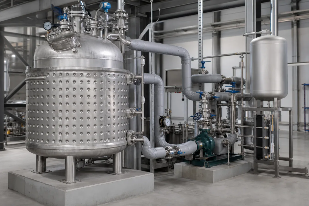
Crystallizer jacket cooling/heating loop: keeping the jacket close enough to the batch that a cooling ramp does not crystallise product on the wall
The circulation loop behind a batch cooling crystallizer: pump, exchanger or circulator, thermal fluid and expansion tank, judged by how closely the vessel contents follow the cooling ramp and how far the jacket has to run ahead of them
In a batch cooling crystallizer the product is made by the temperature trajectory: the solution is held above its saturation temperature to dissolve everything, cooled into the metastable zone, seeded or allowed to nucleate, and then cooled along a set profile to the final temperature. The jacket does that work, but the jacket only follows whatever the circulation loop sends it. This page covers that loop as a system in its own right: a packaged circulator or a skid with a circulation pump, a heating and cooling exchanger and an expansion tank, filled with one heat-transfer fluid that serves both directions. The questions it answers are how fast the contents can be made to follow a ramp, how far ahead of the contents the jacket has to run to get there, and how the fluid inventory is kept safe while it swells and shrinks.
Single-fluid jacket loops (packaged circulator or pump-exchanger skid, thermal fluid and expansion tank) judged by what they do to a batch cooling crystallizer: the lead of jacket over contents during a ramp, jacket undershoot and wall nucleation after scale-up, and how the fluid inventory is held through each heat-and-cool cycle. General-purpose temperature control units and their heating and cooling power are covered on the Jacket temperature control system (temperature control unit) page; seeding recipes, supersaturation control and agitator scale-up on the Automated batch cooling crystallizer page; fired and electric hot-oil heating loops on the Thermal fluid (hot oil) heating system page. Complete jacketed stirred-tank reactors are covered on the Chemical reactor (jacketed stirred tank) page; conventional, dimple and half-pipe jacket constructions on the Heating/cooling jacket for a reactor vessel page; catalyst cartridges and baskets on the Reactor core page.
CNFX editorial research · Sources checked October 13, 2026 · 4 sources
From 60 °C to 20 °C on a set trajectory: the nucleation approach, linear and cubic ramps the loop has to track
Chew and co-workers (Institute of Chemical and Engineering Sciences, Singapore, with AstraZeneca) ran glycine cooling crystallizations in a 500 ml jacketed flask stirred at 550 rpm, with a Julabo HP50 circulator pumping deionised water through the jacket and a Pt100 reading the contents every 2 seconds. [1]
For glycine the authors found hardly any difference in the final chord-length distributions between natural cooling, cubic and linear profiles; they attribute this to glycine's fast growth, estimated at 62 nm/s at 0.3 °C/min, which makes nucleation the controlling step. [1] The same paper notes that crystallizations above 5 litres are conventionally run on a pre-set cooling profile taken from small-scale experiments, and states the paper's purpose as testing whether newer control methods give the more consistent product and easier scale-up claimed for them. [1]
Editorial calculation from the set points above: a linear ramp from 60 °C to 20 °C takes 40 K ÷ 0.7 K/min ≈ 57 minutes at 0.7 °C/min and 40 K ÷ 0.3 K/min ≈ 133 minutes at 0.3 °C/min, so the loop has to hold a stable ramp for one to two hours, not just reach an end temperature. [1]
Step in the glycine runs
Set value
What the loop had to do
Dissolution
Saturation temperature 50 °C; held at 60 °C for at least 30 minutes [1]
State the dissolution, seeding and final temperatures, the ramp rates or profile between them, and whether the controller follows the contents (process) or the jacket outlet.
02
How far ahead of the contents the jacket runs: 6.5 K/min against 2.3 K/min at 20 litres, and wall nucleation after scale-up
Huber's case study CS 92 shows the gap between jacket and contents directly. A Unistat 910w was connected to a 20-litre Buchi Glas Uster jacketed glass reactor holding 15 litres of a silicone-based heat-transfer fluid, stirred at 70 rpm, through two 1.5 m insulated metal hoses, under process control. [3]
Editorial calculation from CS 92: at the start of the ramp the jacket fell about 6.5 ÷ 2.3 ≈ 2.8 times faster than the contents, and at the lowest settled point it stayed 7 K colder (−82 °C against −75 °C). [3] In a crystallizer that lead is the wall running colder than the bulk, which is where unwanted nucleation starts.
Lee, Kim and Bang (Sogang University) describe exactly that at scale-up: because the heat-transfer area per volume falls in a larger crystallizer, the temperature difference between the reactor and the jacket grows and may induce unwanted nucleation on the crystallizer wall. They designed a cooling-holding profile that minimises undershoot of the jacket temperature and tested it scaling from a 100 mL to a 5 L crystallizer. [2]
Editorial calculation, assuming geometrically similar vessels: going from 100 mL to 5 L multiplies the volume by 50 and the linear size by 50^(1/3) ≈ 3.7, so wetted jacket area per litre falls to about 1/3.7 ≈ 27 % of the small vessel's value. [2] To remove heat at the same rate per litre, the jacket must run roughly 3.7 times further below the contents unless the heat-transfer coefficient rises.
Cooling power 4.7 kW at −40 °C, 3.1 kW at −60 °C, 0.9 kW at −80 °C; heating 6.0 kW; range −90 to 250 °C [3]
—
Ask for the jacket-to-contents temperature difference the loop will need at your batch size and ramp, and for a limit on jacket undershoot during seeding and the first part of growth.
03
The expansion tank on a single-fluid loop: up to 30 % swell, 25 % cold level, 75 % hot level
Because one fluid both heats the batch to dissolution and cools it to the end point, its volume changes through every cycle. Eastman (Therminol heat transfer fluids) states that fluid volume can expand by up to 30 % on reaching operating temperature, and gives a 25 % cold-level and 75 % maximum hot-level guideline for the thermal expansion tank, for fluid availability and vapour disengagement. [4]
Eastman also places the expansion tank at the highest point of the system for gas collection and pump performance, names it the main venting point for moisture and low-boiling components, and lists level measurement and overpressure relief as the instrumentation that prevents overfilling. [4]
Editorial calculation from the 25 %/75 % levels: the swell has to fit within half of the tank volume, so the tank must hold at least twice the expansion. For an assumed 300 litres of fluid in the jacket, piping and exchanger and an assumed 10 % expansion across the loop's temperature span, the swell is 30 litres and the tank needs at least 60 litres; at Eastman's upper figure of 30 % it would need 180 litres. [4] The fluid volume and expansion figure here are assumptions for illustration; the real figure comes from the chosen fluid's density at the lowest and highest loop temperatures.
Give the total loop volume (jacket, hoses or piping, exchanger, pump), the fluid, and the lowest and highest loop temperatures so the tank, vent and relief can be sized.
04
What to send for a crystallizer jacket cooling/heating loop
Paste it into your enquiry below or into an email to a maker, then replace every bracket.
Vessel: [volume; jacket type; jacket volume; heat-transfer area]
Profile: [dissolution, seeding and final temperatures; ramp rates or profile]
Control: [process (contents) or jacket; allowed jacket undershoot]
Utilities: [chilled water, brine or refrigeration; steam or electric heat]
Fluid: [type; lowest and highest loop temperature; loop volume]
Skid: [pump; exchanger; expansion tank; hazardous-area rating]
Explore company information and manufacturing capabilities, then discuss the scope of your project with a relevant supplier.
Share this page
Compiled and source-reviewed by the CNFX editorial team.
Each manufacturer above links to the page on that company's own website where the product is listed, with the date we checked it. How we source and review
· Page last updated 13 October 2026
Buyer questions
What cooling rate is used to approach nucleation in a cooling crystallizer?
In the glycine runs by Chew et al., 0.5 °C/min, chosen because it gave a reproducible nucleation temperature and enough nuclei; linear growth ramps were 0.7 °C/min seeded and 0.3 °C/min unseeded. [1]
How much faster does the jacket cool than the contents?
In Huber's CS 92 test on a 20-litre reactor the jacket ramp was over 6.5 K/min against 2.3 K/min for the contents, and the jacket settled 7 K colder (−82 °C against −75 °C). [3]
Why does scale-up cause wall nucleation in a crystallizer?
Lee, Kim and Bang note that heat-transfer area per volume falls in a larger crystallizer, so the reactor-to-jacket temperature difference grows and may nucleate crystals on the wall. [2]
How full should the expansion tank be?
Eastman's guideline is 25 % at the cold level and no more than 75 % at peak operating temperature. [4]
Sources and what still needs a direct check
Sources checked 2026-10-13. Four sources: ramp and seeding values from a glycine study by the Institute of Chemical and Engineering Sciences and AstraZeneca (AIChE 2005), the scale-up abstract by Lee, Kim and Bang of Sogang University (AIChE 2008), Huber's case study CS 92, and Eastman's note on thermal expansion tanks.