Editorial Technical Reference

3D Camera Array

This page explains how 3D Camera Array is classified within Computer, Electronic and Optical Product Manufacturing. Technical values and manufacturer relationships are research references; confirm the current specification and supplier evidence for each order.

Technical Definition & Core Assembly

A multi-camera system that captures synchronized images from multiple angles to generate 3D spatial data.
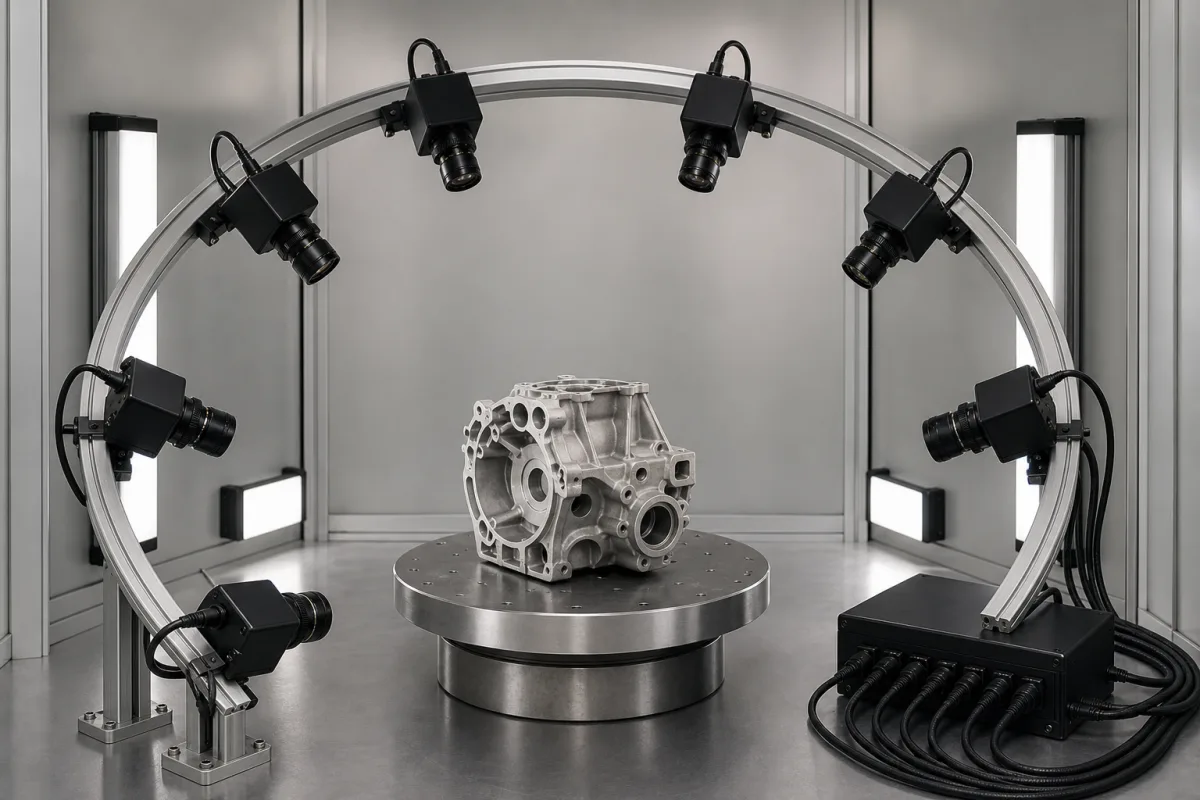
Representative product image. Confirm appearance and specifications with the manufacturer.

Product Specifications

Technical details and manufacturing context for 3D Camera Array

Definition
The 3D Camera Array is a component of the 3D Vision Guidance System, designed for industrial automation applications. It consists of multiple precisely calibrated cameras arranged in a specific configuration to capture synchronized images from different perspectives. By employing stereo vision algorithms and triangulation principles, the array calculates depth information from pixel disparities, enabling real-time reconstruction of three-dimensional coordinates, depth measurement, and object tracking. The array's calibration ensures accurate 3D coordinate reconstruction for guidance and measurement tasks. Key specifications include a camera count of 4 to 16 units, synchronization accuracy of ≤100 microseconds, image resolution of 5 to 12 megapixels, frame rate of 30 to 60 fps, baseline distance of 50 to 500 mm, depth accuracy of ±0.1 to ±1.0 mm at 1 meter distance, operating temperature of 0 to 50 °C, ingress protection rating of IP54 to IP65 per IEC 60529, power supply of 24 V DC ±10%, power consumption of 15 to 60 W, data interface options of GigE or USB 3.0, and weight of 2 to 10 kg. The housing is made of aluminum alloy, with optical glass lenses and CMOS/CCD sensors, and circuit boards. These values are directory reference ranges and must be verified with the legal manufacturer or supplier for the specific model and application. The array is intended for use in industrial environments where precise 3D vision is required, such as robotic guidance, quality inspection, and automated measurement. It is not a standalone product but a critical component that integrates with the broader vision system. Users should confirm compatibility, installation requirements, and environmental suitability with the supplier.
Working Principle
Multiple cameras capture synchronized images of the same scene from different viewpoints. Using stereo vision algorithms and triangulation, the system calculates depth information by comparing pixel disparities between images. The array's precise calibration ensures accurate 3D coordinate reconstruction for guidance and measurement applications. The synchronization accuracy of ≤100 μs ensures temporal alignment for dynamic scenes, and the baseline distance affects depth accuracy and field of view. The system processes images to generate 3D spatial data in real-time.
Common Materials
CMOS/CCD sensors, Optical glass lenses, Aluminum alloy housing, Circuit boards
Technical Parameters
ParameterTypical rangeNotes & selection driver
Number of Cameras4–16 unitsDetermines angular coverage and resolution.
Synchronization Accuracy≤100 μsEnsures temporal alignment for dynamic scenes.
Image Resolution5–12 MPHigher resolution improves detail but increases data rate.
Frame Rate30–60 fpsHigher frame rates for fast motion capture.
Baseline Distance50–500 mmAffects depth accuracy and field of view.
Depth Accuracy±0.1–±1.0 mmAt 1 m distance; degrades with distance.
Operating Temperature0–50 °COutside range may cause thermal drift.
Ingress ProtectionIP54–IP65For dust and water resistance.IEC 60529
Power Supply24 V DC ±10% VStable voltage required for consistent performance.
Power Consumption15–60 WDepends on number of cameras and processing.
Data InterfaceGigE / USB 3.0Determines data transfer rate and cable length.
Weight2–10 kgAffects mounting and portability.

Ranges are indicative industry figures for RFQ preparation, not a supplier commitment. Confirm every value and standard with the legal manufacturer before ordering.

Components / BOM
  • Camera Module
    Individual image capture unit with sensor and lens
    Material: Aluminum alloy, optical glass
  • Synchronization Controller
    Ensures simultaneous image capture across all cameras
    Material: PCB with electronic components
  • Calibration Target
    Reference pattern for camera alignment and calibration
    Material: Glass or ceramic with precision markings
  • Mounting Frame Part
    Precisely positions cameras in the array configuration
    Material: Aluminum alloy
  • Image Processing Unit Optional
    Runs the stereo matching and turns pixel disparity into 3D coordinates on board; some arrays hand raw frames to a host PC instead.

Applied To / Applications

This component is essential for the following industrial systems and equipment:

Industrial Ecosystem & Supply Chain Structure

Complementary Systems
Downstream Applications
Specialized Tooling

Application Fit & Sizing Matrix

Operational Limits
pressure: Atmospheric (non-pressurized)
other spec: IP54 ingress protection, 50-60 Hz power frequency
temperature: 0°C to 40°C
Media Compatibility
✓ Indoor air environments ✓ Clean manufacturing spaces ✓ Laboratory settings
Unsuitable: High-vibration industrial machinery with particulate generation
Sizing Data Required
  • Required field of view dimensions (width × height × depth)
  • Target spatial resolution (mm/pixel)
  • Maximum object velocity for motion capture

Reliability & Engineering Risk Analysis

Failure Mode & Root Cause
Lens contamination and fogging
Cause: Accumulation of dust, oil mist, or moisture on optical surfaces due to inadequate sealing or environmental exposure in industrial settings, leading to image degradation and calibration errors.
Sensor overheating and thermal drift
Cause: Prolonged operation in high-temperature environments or insufficient cooling, causing electronic component degradation, color calibration shifts, and eventual sensor failure.
Maintenance Indicators
  • Progressive image distortion or blurring in multiple camera feeds simultaneously
  • Audible fan failure or abnormal thermal alarms from camera housing indicating cooling system malfunction
Engineering Tips
  • Implement regular optical cleaning schedules with manufacturer-approved solutions and maintain positive pressure purge systems to prevent contaminant ingress
  • Install environmental monitoring with temperature/humidity sensors at array locations and ensure adequate airflow spacing between units to prevent thermal stacking

Indicative industry ranges for design and RFQ preparation. Confirm the exact figures and applicable standard with the manufacturer before specifying.

Compliance & Manufacturing Standards

Applicable Standards
ISO 10360-8:2013 (Geometrical product specifications - Acceptance and reverification tests for coordinate measuring systems) CE Marking (Directive 2014/35/EU for Low Voltage Equipment and 2014/30/EU for Electromagnetic Compatibility)

Quoted from the published standard.

Manufacturing Precision
  • Camera Alignment: +/-0.01° angular deviation
  • Baseline Distance: +/-0.05mm between optical centers
Quality Inspection
  • Photogrammetric Calibration Test using certified reference artifacts
  • EMC (Electromagnetic Compatibility) Immunity Test per IEC 61000-4 series

Manufacturers of 3D Camera Array

Manufacturer profiles associated with 3D Camera Array.

Sourcing 3D Camera Array from China?
Tell us your specification and target quantity — we will match it against manufacturer records and come back with the factories that fit.
Request manufacturers We manufacture this

Manufacturer listings support early research and capability understanding. They are not certification, ranking, or transaction guarantees.

Technical documentation
Request current drawings, revision history, and a signed specification sheet.
Manufacturing capability
Verify equipment lists, process limits, capacity, and representative production evidence.
Inspection readiness
Confirm test methods, calibrated equipment, sampling plans, and traceable reports.
Supplier transparency
Check the legal entity, factory address, ownership, certifications, and direct contacts.

CNFX does not score or rank suppliers. Buyers must verify all claims and documents with the legal manufacturer before ordering.

Supply Chain Compatible Machinery & Devices

Industrial IoT Gateway

The Industrial IoT Gateway is a ruggedized edge computing device designed for industrial environments.

Explore Specs →
Modular Industrial Edge Computing Device

This modular industrial edge computing device is a ruggedized system designed for deployment in harsh industrial environments to perform real-time data processing, analytics, and control functions at the network edge.

Explore Specs →
Industrial Smart Camera Module

The Industrial Smart Camera Module is a compact, self-contained vision processing unit designed for integration into industrial machinery and production lines.

Explore Specs →
Surface Mount Resistor

Passive electronic component for current limiting and voltage division in circuits

Explore Specs →

Frequently Asked Questions

What is the typical number of cameras in the array?

The directory lists a range of 4 to 16 cameras. The exact number depends on the specific model and application requirements. Verify with the manufacturer.

What is the depth accuracy at 1 meter?

The listed depth accuracy is ±0.1 to ±1.0 mm at 1 meter distance. Accuracy degrades with distance, so confirm for your working range.

What data interfaces are available?

The array supports GigE or USB 3.0 interfaces. The choice affects data transfer rate and cable length. Confirm compatibility with your system.

What is the operating temperature range?

The operating temperature is 0 to 50 °C. Outside this range, thermal drift may occur. Ensure the environment meets this specification.

Data Basis

Editorial classification, named public sources where available, and source-reviewed manufacturer records.

Preliminary Technical Classification
This page supports structured research, RFQ preparation, and supplier evaluation. It does not replace buyer-led supplier qualification, standards review, or technical approval.
Buyer enquiry

Request manufacturing insight for 3D Camera Array

Ask for use case, specification boundaries, supplier type, and RFQ preparation information for this product.

Where it goes
Straight to the CNFX editorial desk, and to the manufacturer if this product is linked to a claimed profile. Nothing is broadcast to a supplier list.
Your details stay here
We do not sell or rent enquiry data, and we do not add you to a mailing list. Used only to answer this request.
No commission, no middleman
CNFX is a directory. We take no cut of any order and never negotiate on a supplier's behalf.
What we don't claim
A listing is not an endorsement. Qualify every supplier and verify every figure yourself before ordering.

Your business information is used only to process this request.

Thank you! Your message has been sent. We'll respond within 1–3 business days.
Sorry, we couldn't send your message. Please try again, or email us at contact@cnfx.com.

Need to Manufacture 3D Camera Array?

Compare manufacturer profiles with relevant product and process capability.

First Product
Next Product
3D Pattern Scanner
Get QuotesChat