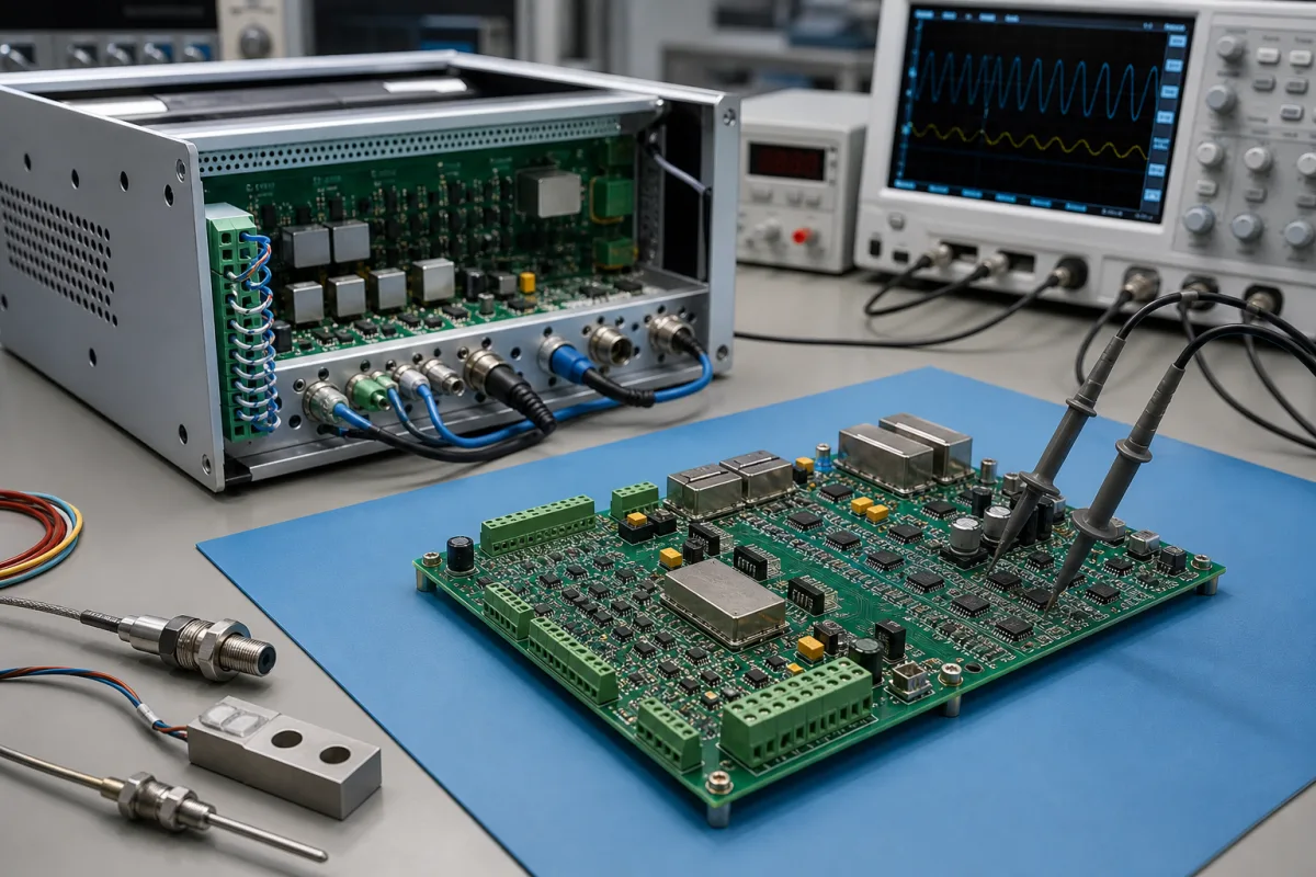
Signal conditioning circuit for IEPE vibration sensors: constant-current excitation, AC coupling, scaling for the ADC and wire-break detection on one board
The board-level front end between an IEPE accelerometer and an ADC · constant-current excitation and compliance voltage, AC coupling and scaling, cable effects, and open- and short-circuit detection
An IEPE sensor carries its own preamplifier and sends its vibration signal back down the same coaxial cable that powers it. The signal conditioning circuit at the other end does four jobs: it sources a constant current at a high enough compliance voltage, strips off the sensor's DC bias with a coupling capacitor, scales and filters the remaining AC signal for the ADC, and watches the DC level to tell a broken cable from a shorted one. These are board-level design choices, and the values chosen set the lowest frequency, the largest signal and the longest cable the channel can handle.
Analog front-end circuits and boards for IEPE (ICP, CCLD-type) accelerometers and other integrated-electronics piezoelectric sensors, as built into data acquisition systems, condition-monitoring modules and PLC special-function modules: current source, AC coupling, gain and level shifting, anti-alias filtering and fault detection. The sensors themselves are covered on the Vibration sensor page and IO-Link vibration sensors on the IO-Link smart vibration sensor page. DIN-rail conditioners and isolators for thermocouple, RTD, current and voltage inputs are covered on the Industrial signal conditioner page; strain-gauge bridge amplifiers on the Load-cell signal conditioner page; general analog input modules on the Analog input module for PLC, remote I/O and data acquisition page; LVDT excitation and demodulation boards on the Signal-conditioning circuit board for LVDT position sensors page; magnetostrictive sensor heads on the Sensor head electronics module page; pyrometer signal processors and pulse-to-analog converters on their own pages. Charge amplifiers for charge-output sensors are outside this page.
CNFX editorial research · Sources checked October 13, 2026 · 3 sources
Constant current, compliance voltage and the sensor's DC bias
Metra describes the IEPE principle as a constant current source, inside the instrument or as a separate unit, feeding the sensor's built-in amplifier over the same coaxial cable that carries the signal back as a modulated bias voltage. [1]
Metra adds that lower current raises the output impedance and with it the susceptibility to EMI, and that for its low-power IEPE variant a 10 to 12 V compliance voltage is sufficient and the current may be as low as 0.1 mA depending on the transducer, which it says can cut transducer power by up to 99%. [1]
Editorial calculation: 4 mA from a 24 V compliance supply is 96 mW per channel, the roughly 100 mW Metra cites; four channels at the 3.5 mA of TIDA-010249 and 24 V draw about 0.34 W for excitation alone, inside that design's stated total of under 1 W.
List the sensors the board must power: their bias voltage, required current and full-scale output, so the compliance voltage leaves room for the largest positive swing above the bias.
02
AC coupling at 0.6 Hz, attenuation to the ADC range and the 20 kHz anti-alias band
In TIDA-010249, a coupling capacitor removes the bias, and a 10:1 resistive divider referenced to the ADC's 2.5 V mid-supply brings ±10 V down to ±1.0 V; a gain-of-2 buffer and a gain-of-2 fully differential amplifier then give ±4.0 V differential into a 24-bit delta-sigma ADC. [3]
TI's TIDA-01471 guide explains that the coupling capacitor and series resistor form the high-pass filter, that its simulation gives a 3 dB cutoff of 0.6 to 0.7 Hz, and that after a step the output has to be discarded while the filter settles: the lower the cutoff, the longer the settling time. [2]
Editorial calculation: the TIDA-010249 chain multiplies ±10 V by 0.1, 2 and 2, giving ±4.0 V and the 0.4 V/V gain in its specification table. [3]
State the lowest vibration frequency you must keep, the highest frequency of interest and the sampling rate of the ADC or module, so the coupling corner, anti-alias filter and settling time are set together.
03
Cable capacitance: when long coax limits output span and bandwidth
Metra gives the output impedance of IEPE transducers as under 100 ohms, so that standard coaxial cable can be used over long runs, and the capacitance of its coaxial cables as about 100 pF/m. At higher cable capacitance the built-in amplifier's slew rate falls, so the full ±6 V span is reached only up to a few hundred hertz on very long cables. Metra says that at 4 mA the span reduction can be neglected up to 10 nF (100 m) and the upper frequency limit is unaffected up to 50 nF (500 m), and that raising the supply current compensates within limits. [1]
Editorial note: on a board with selectable excitation current, such as TIDA-01471's 0–20 mA source, the current setting is the circuit-side remedy for long cables; TI notes that its programmable current and sampling speed are meant to suit different sensor cable distances. [2]
04
Telling a broken sensor cable from a shorted one by the DC level
Because the DC bias sits at a known level, the circuit can watch it. TIDA-01471 extracts the DC level with a low-pass filter at 1.4 Hz, chosen as a trade-off against detection delay, and compares it with thresholds of 11.1 V for an open circuit and 1.8 V for a short circuit using two comparators powered from the same high-voltage supply as the current source; simulation showed under 200 mV of threshold variation. [2] The TIDA-010249 block diagram labels its thresholds 21 V for open and 0.5 V for short. [3]
Editorial note: an open cable lets the current source rise to its compliance voltage and a short pulls the input towards zero, so the two thresholds bracket the sensor's bias; check them against the bias and swing of the sensors you will connect, since the two TI designs place them differently.
Ask how fault status is reported (comparator outputs, register bits or LEDs), the detection delay, and whether the current source is protected against a shorted input.
05
Data for an IEPE signal conditioning circuit
Paste it into your enquiry below or into an email to a maker, then replace every bracket.
Sensors: [bias voltage; sensitivity; full-scale output; required current]
Channels: [number; synchronous sampling needed or not]
Excitation: [current or range; compliance voltage]
Signal: [lowest and highest frequency; input range; gain]
ADC: [resolution; sampling rate; interface]
Cables: [length; capacitance per metre]
Diagnostics: [open and short detection; thresholds; reporting]
Environment: [temperature range; board size; power budget]
Explore company information and manufacturing capabilities, then discuss the scope of your project with a relevant supplier.
Share this page
Compiled and source-reviewed by the CNFX editorial team.
Each manufacturer above links to the page on that company's own website where the product is listed, with the date we checked it. How we source and review
· Page last updated 13 October 2026
Buyer questions
What current and voltage does an IEPE sensor need from the conditioning circuit?
Metra gives 2 to 20 mA constant current at 24 to 30 V compliance; TI's designs specify at least 23 V. [1][2]
Why does an IEPE input have a low-frequency limit?
The coupling capacitor that removes the sensor bias forms a high-pass filter; TI's TIDA-01471 places its cutoff at 0.6 to 0.7 Hz and notes that lower cutoffs settle more slowly. [2]
How does the circuit detect a broken sensor cable?
By filtering out the DC level and comparing it with thresholds; TIDA-01471 uses 11.1 V for open and 1.8 V for short circuit. [2]
Sources and what still needs a direct check
Sources checked 2026-10-13. Metra Mess- und Frequenztechnik's page on the IEPE standard, and two Texas Instruments reference design guides: TIDA-01471 (single channel for PLC analog input, 2017) and TIDA-010249 (four synchronous channels, 2022).