Audio decoder chip: compressed-format decoders that turn MP3, AAC, Ogg Vorbis or Dolby/DTS bitstreams into PCM or analog audio
The chip that unpacks compressed audio · MP3, AAC, Ogg Vorbis, WMA, Dolby and DTS bitstreams turned into PCM or straight into an analog output, compared across a decoder-only IC, a decoder with its own DAC, and a multichannel decoder DSP
A codec converts between analog and PCM; a decoder chip does the step before that, unpacking a compressed file or stream into PCM samples. Some decoders stop there and pass PCM over I2S to a separate DAC, some carry their own DAC and headphone driver so a microcontroller only has to feed bytes over SPI, and some are multichannel DSPs that decode cinema formats for an AV receiver or soundbar. Which kind fits depends on the formats to be played, the number of output channels and the power the product can spend on decoding.
Integrated circuits that decode compressed audio formats (MP3 and other MPEG audio layers, AAC and HE-AAC, Ogg Vorbis, WMA, FLAC, MIDI, Dolby Digital, DTS) into PCM or analog output: decoder-only ICs, decoders with on-chip DAC and earphone driver, and multichannel audio decoder DSPs. Stereo audio codec ICs that convert between analog and PCM without decoding compressed formats are covered on the Audio codec (stereo audio ADC/DAC IC) page; stand-alone DACs, Class-D amplifiers and DSP modules are outside this page.
CNFX editorial research · Sources checked October 13, 2026 · 3 sources
Decoder only, decoder with its own DAC, or multichannel decoder DSP: STA013, VS1053b and CS4953xx side by side
The three parts below cover three different jobs; the output row decides what else has to go on the board.
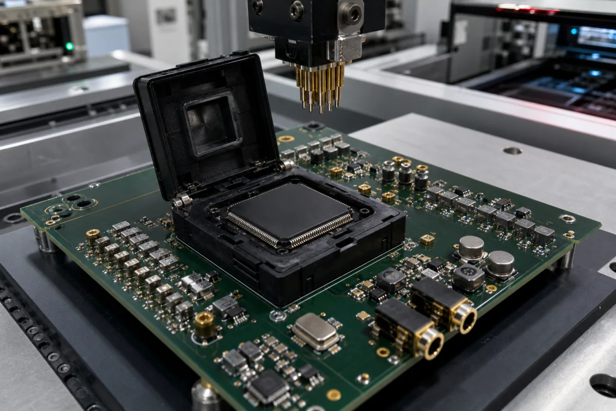
The image above shows a QFP audio IC held in a clamshell test socket on an evaluation board with audio jacks, the arrangement used to try a decoder against real files before committing to a board layout.
The STA013 datasheet notes that its PCM interface is software-programmable to suit the DAC chosen, which is the trade a decoder-only part makes: a free choice of DAC quality, at the cost of a second chip, its clocking and its layout. [2] The VS1053b removes that second chip but fixes the analog performance at what its own DAC delivers (next section). [1]
Item
ST STA013
VLSI Solution VS1053b
Cirrus Logic CS4953xx
Formats decoded
MPEG 1, 2 and 2.5 Layer III (MP3), stereo, dual or mono [2]
Ogg Vorbis, MP3, optional MP1/MP2, AAC-LC and HE-AAC v2, WMA 4.0 to 9 (5–384 kbps), General MIDI, WAV; FLAC with a software plugin [1]
Dolby Digital EX, DTS-ES 96/24 and DTS Neo:6, MPEG-2 AAC LC 5.1, Dolby Pro Logic IIz; selection guide lists Dolby Digital, AAC, MP3 and HDCD for the CS49530x [3]
Bitstream limits
8 to 320 kbit/s; sample rates 48, 44.1, 32, 24, 22.05, 16, 12, 11.025 and 8 kHz [2]
Ogg Vorbis up to 500 kbit/s and 100 Hz to 48 kHz, 2 channels [1]
Up to 12 channels of 32-bit serial audio input [3]
Output
Serial PCM (I2S and other formats) to an external DAC, with an oversampling clock for the DAC [2]
On-chip stereo sigma-delta DAC and earphone driver for a 30 Ω load; I2S output for an external DAC as well [1]
16 channels × 32-bit PCM out, with one or two 192 kHz S/PDIF transmitters [3]
Processing
Digital volume, bass and treble; CRC and sync error detection [2]
VS_DSP4 core with 16 KiB instruction RAM for user code alongside the built-in decoder; up to 8 GPIO [1]
Dual 32-bit DSP, 300 MIPS in the selection guide, 150 MHz internal clock; up to 150 ms lip-sync delay per channel on the CS49531x [3]
0 to +70 °C commercial, −40 to +85 °C automotive grade [3]
List every format, bitrate and sample rate the product must play, the number of output channels, whether the output is analog headphone, line, I2S or S/PDIF, and the host interface available (SPI, I2C, I2S).
02
Clock and power: a 12.288 MHz crystal for 48 kHz, a 4.5× multiplier for HE-AAC v2, 76–85 mW for MP3 only, and a 500 mA core on a Dolby/DTS DSP
Decoding load varies with the format, and the datasheets show it in the clock each chip needs and the power it draws.
The STA013 datasheet gives its power two ways: the feature list says 85 mW at 2.4 V, while the power dissipation table gives 85 mW at ≤48 kHz with VDD = 3 V. Confirm the supply condition with the supplier before using the figure in a battery budget. [2]
Editorial calculation: at the recommended 3.5× multiplier, a 12.288 MHz crystal gives CLKI = 43 MHz on the VS1053b; HE-AAC v2 at 4.5× needs 55.3 MHz, the top of the CLKI range. [1] During Ogg Vorbis playback, 11 mA at the 2.6 V AVDD of the test plus 11 mA at 1.8 V CVDD is about 29 + 20 = 49 mW, before I/O current. [1] On the CS4953xx, 500 mA at 1.8 V is 0.9 W for the core and 120 mA at 3.3 V about 0.4 W for I/O, roughly 1.3 W, some fifteen times the STA013's 85 mW. [3][2]
Item
Stated value
VS1053b input clock
XTALI 12 to 13 MHz (12.288 typ.); must be at least 12.288 MHz to play 48 kHz at correct speed, because the highest correct sample rate is XTALI/256 [1]
VS1053b internal clock
CLKI 12 to 55.3 MHz, multiplier 1.0× to 4.5×; recommended 3.5× plus 1.0× because HE-AAC v2 files need 4.5× to decode both SBR and PS; SBR and PS switch off if the clock is too slow [1]
VS1053b supplies and current
AVDD 2.6–3.6 V, CVDD 1.7–1.85 V, IOVDD 1.8–3.6 V; 128 kbit/s Ogg Vorbis at full volume into 30 Ω: AVDD 11 mA, CVDD 11 mA [1]
STA013 clock
10, 14.31818 or 14.7456 MHz external clock or built-in crystal oscillator; PLL for internal and PCM clocks [2]
STA013 power
76 mW at ≤24 kHz, 79 mW at ≤32 kHz, 85 mW at ≤48 kHz sampling, at VDD = 3 V; supply 2.4 to 3.6 V [2]
CS4953xx supplies and current
Core 1.8 V, PLL 3.3 V, I/O 3.3 V (5 V tolerant); 500 mA core and I/O, 3.5 mA PLL, 120 mA I/O with external memory (typ.) [3]
Give the formats with the highest decoding load (HE-AAC v2, WMA, multichannel Dolby or DTS), the crystal frequency available, the supply rails and the power budget for decoding.
03
On-chip DAC versus I2S out: the VS1053b's 18-bit DAC at 94 dB SNR, and crosstalk that drops from 80 dB to 53 dB on a 30 Ω earphone
When the decoder carries its own DAC, its analog figures become the product's audio figures. The VS1053b datasheet states them at AVDD 3.3 V with a 30 Ω load:
Editorial calculation: 2750 mVpp is about 0.97 V rms for a sine, and into a 30 Ω earphone that is about 31 mW per channel at full-scale output; with VREF at 1.23 V the 2050 mVpp output is about 0.72 V rms. [1] The datasheet gives 80 dB of channel separation with a 600 Ω load and 53 dB with a 30 Ω load, both measured through the GBUF output buffer; a product that needs more separation on headphones can take the I2S output to an external DAC and amplifier instead. [1]
Neither the STA013 nor the CS4953xx has an analog output; their analog quality is set entirely by the DAC and amplifier that follow them. [2][3]
Explore company information and manufacturing capabilities, then discuss the scope of your project with a relevant supplier.
Share this page
Compiled and source-reviewed by the CNFX editorial team.
Each manufacturer above links to the page on that company's own website where the product is listed, with the date we checked it. How we source and review
· Page last updated 13 October 2026
Buyer questions
What is the difference between an audio decoder chip and an audio codec?
A decoder chip unpacks compressed formats such as MP3, AAC or Dolby Digital into PCM, and may add a DAC; a codec converts between analog and PCM. The VS1053b does both: it decodes MP3, AAC, Ogg Vorbis and WMA and also has a stereo ADC and DAC. [1]
Does an MP3 decoder chip need an external DAC?
Some do: ST's STA013 outputs PCM over I2S for an external DAC, while VLSI Solution's VS1053b has an 18-bit on-chip DAC that drives a 30 Ω earphone. [2][1]
How much power does an MP3 decoder IC use?
ST gives 76 mW at up to 24 kHz and 85 mW at up to 48 kHz sampling for the STA013 at 3 V. [2]
Which chips decode Dolby Digital and DTS?
Multichannel decoder DSPs such as Cirrus Logic's CS4953xx, which decodes Dolby Digital EX and DTS-ES 96/24 and outputs 16 channels of 32-bit PCM. [3]
Sources and what still needs a direct check
Sources checked 2026-10-13. Three datasheets from three chip makers: VLSI Solution's VS1053b (version 1.33, 2025), STMicroelectronics' STA013 (distributor-hosted copy) and Cirrus Logic's preliminary CS4953xx data sheet (DS705PP6, 2009).