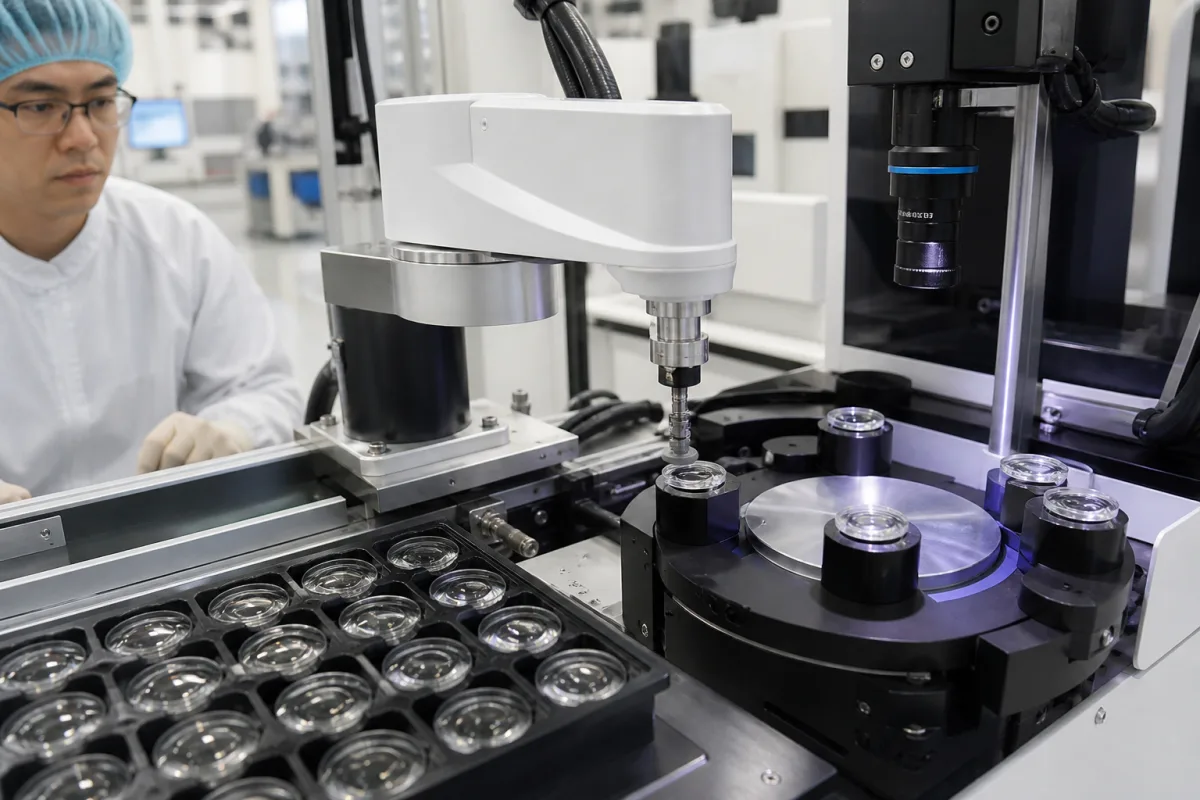
Automated lens loader for centering and surfacing machines: the robot cell that takes a lens off a pallet, pre-centres it and swaps it into the spindle
Robot loaders for lens centering, generating and polishing machines · 2.7 mm to 130 mm working ranges, ±0.015 to ±0.03 mm placing, DIN flat pallets, double suction cups and pre-centring stations
In a centering or surfacing cell the spindle does the precision work, but someone has to put each lens in and take it out. A lens loader replaces that hand: it picks the next blank from a tray, centres it so the machine's clamp receives it on axis, exchanges it for the finished lens in one visit to the work area, and puts the finished lens back on a tray, so a whole batch runs without an operator at the door.
Robot loading and unloading cells built onto lens centering machines, curve generators, polishers and interferometers: working diameter range, placing accuracy, payload, gripper and suction cup layout, pre-centring station, pallet and drawer storage, cleaning stations and the interface to the machine control. The camera and height sensors that locate a lens for loading are covered on the Vision/sensor system for lens loading page; the bell-clamp centering and edging machine itself on the Precision optical lens centering machine page; lens loading, gripping and centring fixtures that feed a camera-module alignment station on the Active optical alignment station page. Cobot cells that queue parts for a coordinate measuring machine are covered on the Robotic part handler for a coordinate measuring machine page.
CNFX editorial research · Sources checked October 13, 2026 · 6 sources
From 2.7 mm endoscope lenses to 130 mm optics: working range, placing accuracy and payload of five loader and loader-equipped machine types
Loaders are built for a band of lens diameters, matched to the machine they serve. The smallest of OptoTech's loaders, the SR 20, is mounted directly on its DZM 20 CNC and WZM 20 CNC micro-centering machines and uses a vacuum gripper designed for micro-optics and endoscopy lenses. [1]
Editorial calculation from the OptoTech figures: ±0.03 mm is about 1.1 % of the diameter of a 2.7 mm lens but about 0.15 % of a 20 mm lens and 0.023 % of a 130 mm lens, so the same placing figure is far tighter in relative terms at the top of the SR 80's range than at the bottom of the SR 20's. [1][2]
Three of the four OptoTech loaders take blocked lenses as well as loose ones: the RPL 30 and RPL 80 handle single surfaces or lenses on cementing pieces, and the SR 80 single surfaces or blocked runners. [3][4][2] Laser Focus World's 2017 product note on the Nakamura-Tome LC-50 and LC-120, sold by OptiPro Systems, gives lens ranges but no accuracy figure, and describes the robot and stocker as combined to save space. [5]
State the smallest and largest lens diameter, whether lenses arrive loose or on cementing pieces, and the mass of the heaviest lens with its block; compare these with the loader's working range and payload, not only with the machine's.
02
One visit to the work area, two lenses: double suction cups, a pre-centring station and the hand-off to the machine control
The sequence OptoTech publishes for the SR 20 has four steps: pick the lens from a DIN pallet or the user's own pallet system; centre it in a separate pre-centring station; take the processed lens out of the machine's work area and insert the new one; put the processed lens on the pallet and pick up the next. Its vacuum gripper holds two lenses at once, one unprocessed and one finished, to shorten the travel. [1]
The larger loaders keep that order and add steps around it. The SR 80 and RPL 80 can clean the finished lens before it goes back to the pallet, in a station with water and air, a second station with a rotating sponge and cloth, or an ultrasonic dip tank on the SR 80 and a surfactant basin on the RPL 80, all optional; the RPL 80 adds a gripper cleaning station and an optional RFID reader and writer for cementing pieces with an RFID tag. [2][4]
On the RPL 30 the double suction cup is Teflon-coated, which OptoTech says minimises carry-over of polishing agent, a 3-point gripper with interchangeable jaws centres the lens before loading, and two optional ejection drawers let lenses be pulled out for measurement without stopping the robot. [3]
The loader works as part of the machine's automatic cycle, not beside it. OptoTech connects its loaders through an interface to the machine control, naming Siemens or Beckhoff controls for the SR 80, and teaches positions from a detachable 12-inch touch pad or by guiding the robot by hand. [2][1]
Ask whether the gripper exchanges finished and new lens in one visit, how the lens is pre-centred (station, 3-point gripper or none), and which machine control the loader interfaces with.
03
How many lenses a batch holds: 200 × 300 mm DIN flat pallets, drawers of large pallets and transport belts
OptoTech states each loader's storage in DIN flat pallets of 200 × 300 mm, inserted and removed by hand.
The SR 20 takes 2 such pallets, the SR 80 up to 4 and the RPL 80 up to 2, or one 300 × 400 mm pallet, or a transport belt. The RPL 30 has up to 5 drawers, each holding 2 large 300 × 400 mm or 4 small 300 × 200 mm DIN pallets, and an optional dip tank that holds up to 4 pallets with water circulation and ultrasonic cleaning. [1][2][4][3] Editorial calculation: fully equipped, the RPL 30's drawers hold 10 large or 20 small pallets, against 2 small pallets on the SR 20.
TRIOPTICS described the same shift when it showed robot loading for its OptiCentric 100 centring tester and ATS 100 adjusting lathe at Optatec in June 2018. Its ATS product manager, Dr. Christian Buß, said the robots take over exactly the loading and unloading step, so that complete lens series are processed in one operation while the user does other work or loads lens trays into other systems. [6]
Give the lenses per batch and the tray format you already use; a loader that accepts your own pallet system avoids re-traying lenses between process steps.
04
Data for an automated lens loader
Paste it into your enquiry below or into an email to a maker, then replace every bracket.
Machine: [make, model and control of the centering machine, generator, polisher or interferometer]
Lenses: [diameter range; thickness; mass; loose or on cementing pieces]
Accuracy: [placing tolerance the machine clamp needs]
Gripper: [suction cup material; double gripper; pre-centring method]
Storage: [pallet format; lenses per batch; drawers or belt]
Options: [cleaning station; RFID; ejection for measurement]
Explore company information and manufacturing capabilities, then discuss the scope of your project with a relevant supplier.
Share this page
Compiled and source-reviewed by the CNFX editorial team.
Each manufacturer above links to the page on that company's own website where the product is listed, with the date we checked it. How we source and review
· Page last updated 13 October 2026
Buyer questions
What lens sizes can an automated lens loader handle?
It depends on the model: OptoTech lists 2.7–20 mm for the SR 20, 10–80 mm for the RPL 80 and 10–130 mm for the SR 80; Nakamura-Tome's LC-50 and LC-120 cover 2–55 mm and 30–120 mm. [1][4][2][5]
How accurately does a lens loader place the lens?
OptoTech gives ±0.03 mm for the SR 20 and SR 80, ±0.02 mm for the RPL 30 and ±0.015 mm for the RPL 80, and adds a pre-centring step before the lens enters the machine. [1][2][3][4]
Why does a lens loader have a double suction cup?
So it can carry the new lens in and the finished lens out in one visit to the work area; OptoTech says this shortens the travel. [1]
How are lenses stored on the loader?
On 200 × 300 mm DIN flat pallets, 300 × 400 mm pallets, drawers or a transport belt, depending on the OptoTech model. [2][3][4]
Sources and what still needs a direct check
Sources checked 2026-10-13. OptoTech technical data sheets for the SR 20, SR 80, RPL 30 and RPL 80 loaders, a Laser Focus World product note on Nakamura-Tome's LC-50 and LC-120 centering machines, and a TRIOPTICS press release on robot loading of its centring tester and adjusting lathe.