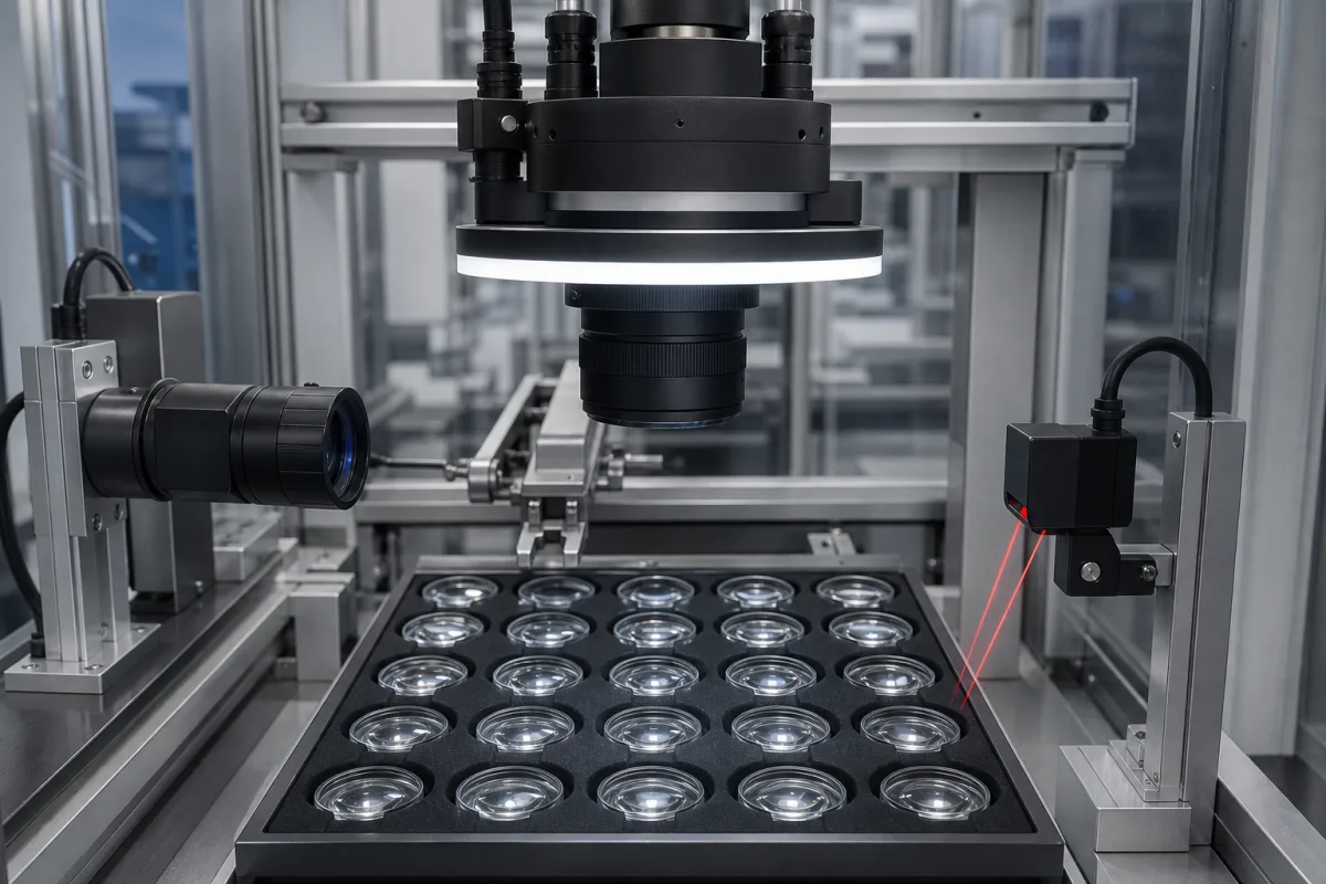
Vision/sensor system for lens loading: camera positioning plus laser or probe height sensing
Vision and laser sensing for automated lens loaders · lens centre and rotation from edge points, height from a laser displacement sensor or touch probe, micrometre repeatability
A vision/sensor system in an automated lens loader is the set of cameras, lighting and distance sensors that tell the handling robot where each lens sits in its tray or fixture, how it is rotated, whether it is present and right side up, and how high its surface is, so it can be picked and placed without touching the optical faces in the wrong place. Ask three things first: what position and rotation tolerance the next station needs, whether height must be measured as well as X–Y position, and how the transparent lens will be made visible to the camera.
Camera and sensor modules that detect, identify and position optical lenses and similar rotationally symmetric optical parts for loading into machines and fixtures, specified by positioning repeatability, field of view, pixel size and height-sensing method. Camera-based inspection, measurement and guidance systems for production lines, with EMVA 1288 camera data and exposure against conveyor speed, are covered on the Machine vision system for inspection page. Lens defect inspection, interferometric surface testing and stand-alone vision measuring machines are outside this page.
CNFX editorial research · Sources checked October 12, 2026 · 3 sources
Centre the lens from its edge: pixel size, magnification and tested repeatability
A 2025 study in Micromachines on positioning optical workpieces for magnetorheological finishing used a 5472 × 3648 camera with 2.4 µm pixels behind a 220 mm lens at 0.5× magnification. The image was closed, binarised with an automatically chosen threshold, edge-detected and fitted with polynomials to give the workpiece centre and its rotation from a marker; over 20 repeated trials the vision module repeated to 1.3 µm in X, 3.7 µm in Y and 0.005° in rotation (3σ). [1]
Editorial calculation: 2.4 µm pixels at 0.5× correspond to 4.8 µm on the part, so the 5472 × 3648 sensor covers about 26.3 × 17.5 mm per image; the study captured two images along the machine X and Y axes to locate a 100 mm diameter part. [1] A lens loader picking small lenses from a tray would trade field of view against that pixel footprint; ask the supplier to state the object-side pixel size and field of view for your lens diameter.
The same study derived the positioning tolerances its polishing process could accept: X and Y errors up to 10 µm, Z up to 5 µm, tilt about A and B up to 0.005° and rotation about C up to 0.01°, applicable to optical parts under 300 mm diameter. [1] Editorial note: those limits belong to polishing; a loader feeding an assembly, coating or blocking station has its own limits, and the vision system should be specified against them rather than against a camera's resolution.
Give the supplier lens diameter range, thickness and surface type (plano, spherical, aspheric), coating, tray or fixture drawing, required X–Y, height and rotation tolerance at the receiving station, cycle time per lens, whether side (convex or concave up) must be detected, and the robot or stage controller the results go to.
02
Add height sensing the camera cannot give: laser triangulation or a touch probe
A top camera gives X, Y and rotation but not height. In the Micromachines study a Renishaw LP2 touch-trigger probe (1 µm repeatability, 5.85 N trigger force) measured the surface at 9 points after the vision step, against 25 in an earlier probe-only method, and the combined method raised the convergence ratio by 41.9% on flat parts and 25.7% on curved ones while cutting alignment time by 66.7% and 80%. [1]
Where nothing may touch the optical surface, a laser displacement sensor measures height or presence. Panasonic's HG-C1030 CMOS micro laser sensor works at a 30 mm centre distance over ±5 mm with 10 µm repeatability, ±0.1% F.S. linearity, an approximately ø50 µm spot, response time switchable between 1.5, 5 and 10 ms, IP67, and operation from −10 to +45 °C. [2]
Micro-Epsilon's optoNCDT 1420 in its 10 mm range model (20–30 mm from the sensor) states 0.5 µm repeatability and linearity below ±8 µm, measuring rates selectable up to 8 kHz (4 kHz on laser class 1 models), and outputs including RS422, EtherCAT, PROFINET and EtherNet/IP; the repeatability figure is given at 1 kHz with a median of 9, and operation is 0 to +50 °C. [3] Editorial note: on a clear lens a triangulation spot can return from both surfaces or from the tray beneath; ask the supplier to demonstrate the sensor on your lens material and coating.
03
Camera, laser and probe figures side by side
Each sensor in the module answers a different question, and the published repeatability spans more than an order of magnitude.
Sensor
What it measures
Published figures
Area camera, 2.4 µm pixels, 0.5× lens
Centre and rotation from edges
1.3 µm X, 3.7 µm Y, 0.005° C repeatability (3σ). [1]
Explore company information and manufacturing capabilities, then discuss the scope of your project with a relevant supplier.
Share this page
Compiled and source-reviewed by the CNFX editorial team.
Each manufacturer above links to the page on that company's own website where the product is listed, with the date we checked it. How we source and review
· Page last updated 13 October 2026
Buyer questions
How repeatable can vision-based centring of an optical part be?
In a Micromachines study, a 5472 × 3648 camera with 2.4 µm pixels at 0.5× repeated to 1.3 µm in X, 3.7 µm in Y and 0.005° in rotation (3σ). [1]
Why add a laser sensor or probe to the camera?
A top camera gives X, Y and rotation but not height; the study added a touch probe, while laser sensors such as Panasonic's HG-C1030 measure height without contact. [1][2]
How precise are small laser displacement sensors?
Panasonic lists 10 µm repeatability for the HG-C1030; Micro-Epsilon lists 0.5 µm for the 10 mm range optoNCDT 1420. [2][3]
Sources and what still needs a direct check
Sources checked 2026-10-12. The vision and probe figures come from a peer-reviewed engineering study of optical workpiece positioning; the laser sensor figures come from Panasonic and Micro-Epsilon product data.