Editorial Technical Reference

Automated Lens Mounting Fixture

This page explains how Automated Lens Mounting Fixture is classified within Computer, Electronic and Optical Product Manufacturing. Technical values and manufacturer relationships are research references; confirm the current specification and supplier evidence for each order.

Technical Definition & Core Assembly

A precision mechanical fixture that automatically holds, positions, and secures optical lenses during mounting in an inspection system.

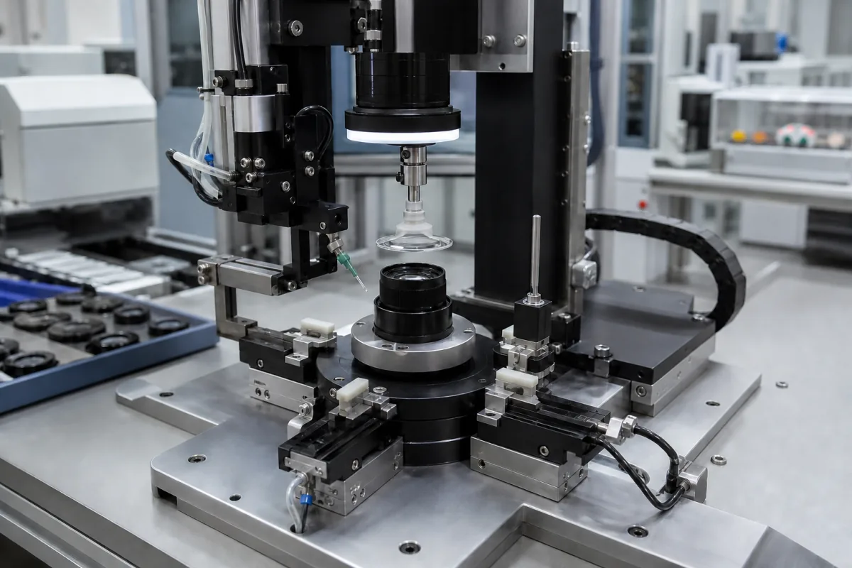
Representative product image. Confirm appearance and specifications with the manufacturer.

Product Specifications

Technical details and manufacturing context for Automated Lens Mounting Fixture

Definition
The Automated Lens Mounting Fixture is a critical component of the Precision Optical Lens Inspection and Measurement System. Its primary role is to provide automated, repeatable, and secure handling of optical lenses during the mounting phase prior to inspection. It ensures lenses are held in a precise, predefined orientation and location, eliminating manual handling errors and enabling high-throughput, automated measurement workflows. It interfaces with robotic arms or conveyors to receive lenses, clamps them without inducing stress or contamination, and presents them correctly to subsequent inspection stations such as interferometers or imaging systems. The fixture is designed for use in computer, electronic, and optical product manufacturing environments. It is a component-level product, typically integrated into a larger inspection system. The fixture operates via pneumatic or servo-electric actuation, using precision alignment pins or optical sensors to confirm lens position, then compliant clamping jaws or vacuum chucks secure the lens periphery without contacting critical optical surfaces. Fine-adjustment mechanisms, such as tip-tilt stages, achieve micron-level positioning accuracy. A control system, often integrated with the main inspection PLC, coordinates clamping force, position verification, and handshake signals with upstream and downstream modules. The fixture is constructed from materials such as stainless steel (304/316), anodized aluminum alloy, and engineering plastics like PEEK or Delrin. Key parameters include operating pressure of 1.0–1.6 MPa, clamping force of 500–2000 N, positioning accuracy of ±0.01 mm, repeatability of ±0.005 mm, lens diameter range of 5–50 mm, cycle time of 2–5 seconds, supply voltage of 24 V DC ±10%, operating temperature of 5–40 °C, ingress protection of IP54–IP65 (per IEC 60529), and weight of 15–25 kg. The footprint is 300x200x150 mm. These values are reference ranges and must be verified for the specific model and application. Always confirm model-specific values and standards with the legal manufacturer or supplier.
Working Principle
The fixture typically operates via a pneumatic or servo-electric actuation system. Upon receiving a lens from a feeder or robot, precision alignment pins or optical sensors confirm the lens's rough position. Actuators then drive compliant clamping jaws or vacuum chucks to secure the lens periphery without contacting critical optical surfaces. The fixture may include fine-adjustment mechanisms (e.g., tip-tilt stages) to achieve micron-level positioning accuracy as required by the inspection system's metrology head. A control system, often integrated with the main inspection PLC, coordinates the clamping force, position verification, and handshake signals with upstream and downstream modules.
Common Materials
Stainless Steel (304/316), Anodized Aluminum Alloy, Engineering Plastics (e.g., PEEK, Delrin)
Technical Parameters
ParameterTypical rangeNotes & selection driver
Clamping Force500–2000 NAdjustable per lens size
Positioning Accuracy±0.01 mmCritical for optical alignment
Repeatability±0.005 mmEnsures consistent mounting
Lens Diameter Range5–50 mmStandard range; custom sizes available
Cycle Time2–5 sPer lens mounting cycle
Supply Voltage24 ±10% V DCFor solenoid valves and sensors
Operating Temperature5–40 °CNon-condensing environment
Ingress ProtectionIP54–IP65Dust and splash proofIEC 60529
MaterialAluminum 6061, Stainless Steel 304Corrosion resistantASTM B221, ASTM A276
Weight15–25 kgDepends on configuration
Footprint300x200x150 mmLength x Width x Height

Ranges are indicative industry figures for RFQ preparation, not a supplier commitment. Confirm every value and standard with the legal manufacturer before ordering.

Components / BOM
  • Base Frame Part
    Provides rigid structural foundation and mounting points to the inspection system.
    Material: Aluminum Alloy
  • Clamping Mechanism (Jaws/Chuck)
    Actuated components that make contact with the lens edge to hold it securely.
    Material: Stainless Steel with Polymer Tips
  • Actuator (Pneumatic Cylinder/Servo Motor)
    Provides the motive force to open/close the clamping mechanism.
    Material: Steel, Aluminum
  • Position Sensor
    Detects the presence and rough position of the lens for the control system.
    Material: Plastic, Electronic Components
  • Fixture Control System
    Sets clamping force, verifies position, and handshakes with the upstream and downstream modules.
  • Alignment Pins Optional
    Give a mechanical rough-position reference where optical sensing is not used.
  • Tip-Tilt Stage Optional
    Fine-adjusts lens tilt to reach micron-level alignment for the metrology head.

Industrial Ecosystem & Supply Chain Structure

Complementary Systems
Downstream Applications
Specialized Tooling

Application Fit & Sizing Matrix

Operational Limits
pressure: Max 0.5 bar clamping force, vacuum hold-down optional
other spec: Lens diameter range: 5-150mm, positioning accuracy: ±2μm, cycle time: 3-8 seconds
temperature: +5°C to +40°C
Media Compatibility
✓ Optical glass lenses ✓ Polycarbonate lenses ✓ Quartz/Silica lenses
Unsuitable: Abrasive slurry environments with >5% particulate concentration
Sizing Data Required
  • Lens diameter and edge thickness
  • Required positioning accuracy (μm)
  • Production cycle time requirement

Reliability & Engineering Risk Analysis

Failure Mode & Root Cause
Misalignment-induced wear
Cause: Incorrect calibration or mechanical drift causing misalignment between lens and mount, leading to excessive friction, scoring, and premature component degradation during automated insertion cycles.
Actuator or servo system failure
Cause: Overloading, electrical surge, or thermal stress on precision motors and drives from repeated high-torque operations, resulting in burnt windings, bearing seizure, or encoder malfunction.
Maintenance Indicators
  • Audible grinding or clicking noises during lens insertion cycles, indicating mechanical interference or worn drive components.
  • Visible lens seating inconsistency or skewed positioning post-mounting, suggesting alignment drift or fixture wear.
Engineering Tips
  • Implement a routine calibration schedule using laser alignment tools to verify and adjust fixture positioning, ensuring minimal tolerance deviation and reducing wear.
  • Install condition monitoring sensors (vibration, temperature) on critical actuators and drives to enable predictive maintenance and prevent catastrophic failures.

Indicative industry ranges for design and RFQ preparation. Confirm the exact figures and applicable standard with the manufacturer before specifying.

Compliance & Manufacturing Standards

Applicable Standards
ISO 10110-7:2017 (Optics and photonics - Preparation of drawings for optical elements and systems - Surface imperfection tolerances) ANSI/ASME B46.1-2019 (Surface Texture, Surface Roughness, Waviness, and Lay) DIN 3140-5:2019 (Dimensions and tolerances for optical components - Mounting of optical components)

Quoted from the published standard.

Manufacturing Precision
  • Bore concentricity: +/-0.01mm
  • Mounting surface flatness: 0.005mm
Quality Inspection
  • Coordinate Measuring Machine (CMM) dimensional verification
  • Laser interferometry for alignment accuracy

Manufacturers of Automated Lens Mounting Fixture

Manufacturer profiles associated with Automated Lens Mounting Fixture.

Sourcing Automated Lens Mounting Fixture from China?
Tell us your specification and target quantity — we will match it against manufacturer records and come back with the factories that fit.
Request manufacturers We manufacture this

Manufacturer listings support early research and capability understanding. They are not certification, ranking, or transaction guarantees.

Technical documentation
Request current drawings, revision history, and a signed specification sheet.
Manufacturing capability
Verify equipment lists, process limits, capacity, and representative production evidence.
Inspection readiness
Confirm test methods, calibrated equipment, sampling plans, and traceable reports.
Supplier transparency
Check the legal entity, factory address, ownership, certifications, and direct contacts.

CNFX does not score or rank suppliers. Buyers must verify all claims and documents with the legal manufacturer before ordering.

Supply Chain Compatible Machinery & Devices

Industrial Smart Camera Module

The Industrial Smart Camera Module is a compact, self-contained vision processing unit designed for integration into industrial machinery and production lines.

Explore Specs →
Surface Mount Resistor

Passive electronic component for current limiting and voltage division in circuits

Explore Specs →
Surface Mount Capacitor

A surface mount capacitor is a fundamental electronic component used for energy storage, filtering, coupling, and decoupling in electronic circuits.

Explore Specs →
Surface Mount Technology (SMT) Pick-and-Place Machine

Automated machine that precisely places electronic components onto printed circuit boards.

Explore Specs →

Frequently Asked Questions

What is the primary function of the Automated Lens Mounting Fixture?

It automatically holds, positions, and secures optical lenses during the mounting phase before inspection, ensuring precise orientation and location to enable automated measurement workflows.

How does the fixture avoid damaging optical surfaces?

It uses compliant clamping jaws or vacuum chucks that contact only the lens periphery, not the critical optical surfaces, and applies controlled clamping force to avoid stress or contamination.

What are the typical operating pressure and clamping force ranges?

The operating pressure is typically 1.0–1.6 MPa, and the clamping force is adjustable from 500 to 2000 N, depending on lens size.

What is the positioning accuracy and repeatability?

The positioning accuracy is ±0.01 mm, and repeatability is ±0.005 mm, ensuring consistent mounting for precise inspection.

Data Basis

Editorial classification, named public sources where available, and source-reviewed manufacturer records.

Preliminary Technical Classification
This page supports structured research, RFQ preparation, and supplier evaluation. It does not replace buyer-led supplier qualification, standards review, or technical approval.
Buyer enquiry

Request manufacturing insight for Automated Lens Mounting Fixture

Ask for use case, specification boundaries, supplier type, and RFQ preparation information for this product.

Where it goes
Straight to the CNFX editorial desk, and to the manufacturer if this product is linked to a claimed profile. Nothing is broadcast to a supplier list.
Your details stay here
We do not sell or rent enquiry data, and we do not add you to a mailing list. Used only to answer this request.
No commission, no middleman
CNFX is a directory. We take no cut of any order and never negotiate on a supplier's behalf.
What we don't claim
A listing is not an endorsement. Qualify every supplier and verify every figure yourself before ordering.

Your business information is used only to process this request.

Thank you! Your message has been sent. We'll respond within 1–3 business days.
Sorry, we couldn't send your message. Please try again, or email us at contact@cnfx.com.

Need to Manufacture Automated Lens Mounting Fixture?

Compare manufacturer profiles with relevant product and process capability.

Previous Product
XY Positioning Stage
Last Product
Get QuotesChat