SMT lines · Rated versus real placement speed, oven conveyor speed, line balance, board flow between machines, profiling
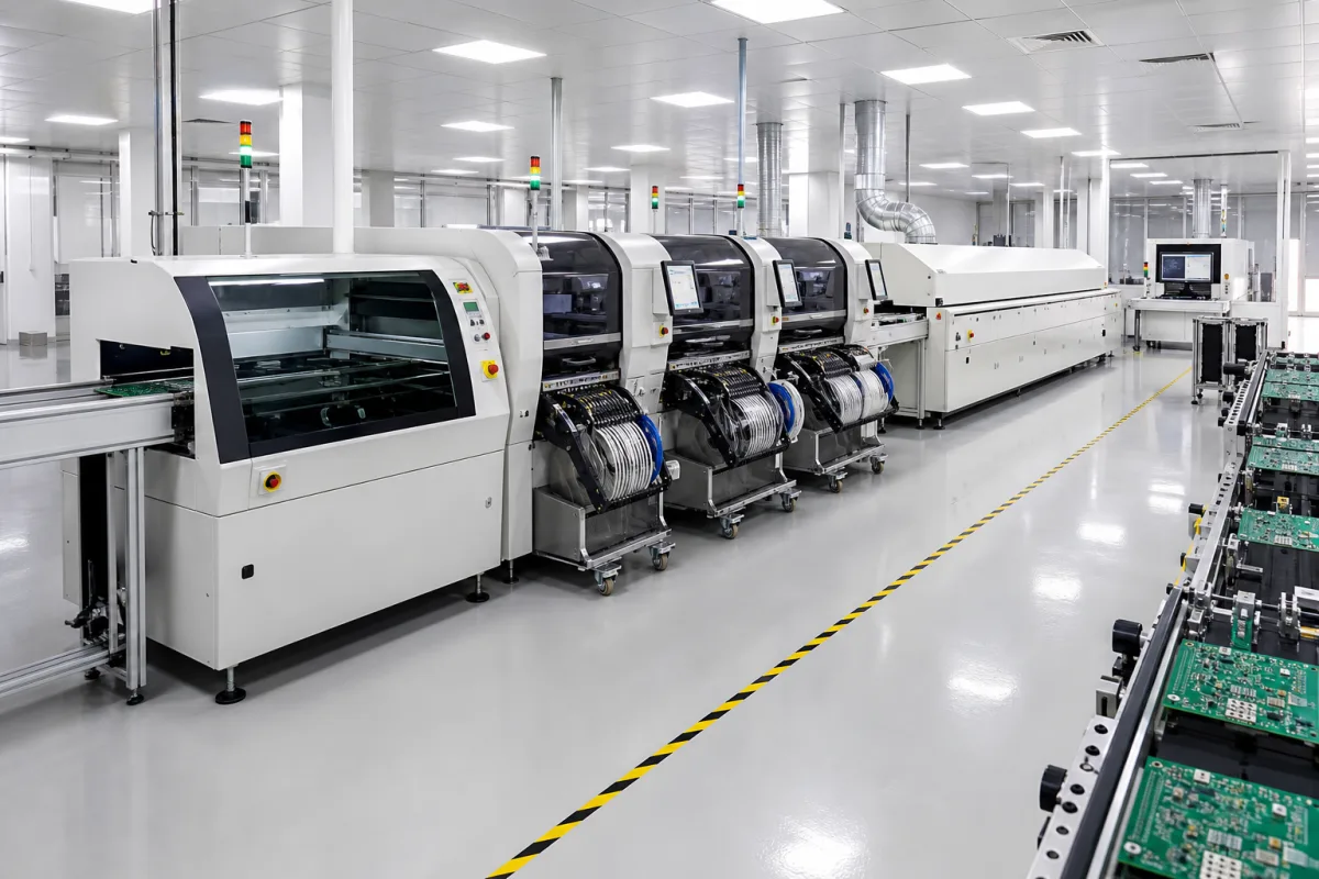
An automated SMT assembly line is a chain of machines joined by conveyors that prints solder paste onto bare boards, places surface-mount components, reflows the solder and inspects the result, with loaders and unloaders at the ends. Ask three things first: which machine limits the line's output for your boards, how the reflow oven's conveyor speed fits that output, and how boards and product data pass between machines from different makers.
Complete or partial SMT lines: board loaders, solder paste printers, placement machines, reflow ovens, inspection and conveyors, supplied as a configured line. Single machines are covered on their own pages (placement head, solder paste printer, reflow oven); PCB assembly services are outside this page.
CNFX editorial research · Sources checked October 11, 2026 · 4 sources
Yamaha's specification for its YSM20R (now discontinued) gives 95,000 CPH with two beams and two high-speed heads, and a mounting accuracy of ±0.035 mm (±0.025 mm) at Cpk ≥ 1.0 (3σ), both under optimum conditions as defined by Yamaha Motor, the accuracy with standard evaluation materials. It takes boards from L50 × W50 to L810 × W490 mm and up to 140 component types (8 mm tape feeder equivalent) on a fixed plate. [1]
The reflow oven also sets a pace. Kester's profile guidance says to measure the heated tunnel and divide its length by 3.5 and by 4 minutes; the result is the conveyor speed range that lets the profile end in the last zone at 3.5–4 minutes and uses the whole oven. [2]
Editorial calculation: a board with 600 placements takes 600 ÷ 95,000 h ≈ 22.7 s on that mounter at its rated speed. An oven with a 3.0 m heated tunnel runs at 0.75–0.86 m/min under the Kester rule; with boards at 0.3 m pitch that is 2.5–2.9 boards per minute, or about 21–24 s per board. Here the rated mounter and the oven are about even, so a mounter running below its optimum rating would become the bottleneck; ask suppliers to simulate your boards. [1][2]
Give the supplier your board sizes and panelisation, placements per board and component mix (smallest chip, largest part, odd-form parts), number of feeder slots needed, target boards per hour, product changeovers per shift, solder alloy, inspection needs, floor space, power and air supply.
02
Check that the paste printer keeps pace with placement
The solder paste printer is the first process step and can pace the whole line. ASMPT's page for its DEK TQ XL large-format stencil printer gives the figures a line plan needs: boards up to 850 × 610 mm, up to 8 mm thick and up to 12 kg, warpage compensation up to 4 mm, a wet print accuracy of ±20 µm at 2.0 Cpk, and a core cycle time of 12 s with a full cycle time of 22.4 s. ASMPT states that cleaning processes and motion sequences are coordinated to keep the cycle stable. [4]
Editorial calculation: a full cycle of 22.4 s is 3,600 ÷ 22.4 ≈ 161 boards per hour. Against the example above, where a 600-placement board takes about 22.7 s on the mounter at its rated speed, the printer is only 0.3 s faster, so any stencil cleaning beyond the stated cycle would make the printer the bottleneck. The printer's 850 × 610 mm board limit also exceeds the 810 × 490 mm maximum of the Yamaha mounter, so the smallest board limit in the line sets the panel size. [4][1]
Link board flow, changeover and profiling between machines
The Hermes Standard (IPC-HERMES-9852) is an open, non-proprietary protocol based on TCP/IP and XML for machine-to-machine communication in SMT lines. Its initiative describes it as the next-generation successor to IPC-SMEMA-9851 board handover, passing board data such as dimensions and IDs along mixed-vendor lines so barcodes need not be read again at each machine; version 1.0 was released in April 2017 and it can be implemented without licence fees. [3]
Yamaha lists optional compatibility with the SEMI SMT-ELS communication standards for its mounter, giving automatic program changeover with other companies' machines. [1] Editorial note: if the line mixes vendors, write the protocol (SMEMA, Hermes, SMT-ELS) and the data each machine must exchange into the order.
For the oven, Kester lists a calibrated profiler with at least four thermocouple ports and a populated board representative of production, with thermocouples at the board's leading and trailing edges and at its largest and smallest thermal masses. Its chart puts a lead-free profile peak at 235–255 °C against a 217 °C liquidus, compared with 205–215 °C and 183 °C for leaded paste. [2]
04
Compare what suppliers offer
Suppliers linked to this page list SMT line equipment; each card links to the page reviewed.
Listings include complete SMT line configurations, desktop and production pick-and-place machines with printers and reflow ovens, and board loaders, unloaders and conveyors.
05
Trace the line components
This is a functional reference built from the sources cited; it is not one maker's specification.
Fill the specification fields with values for your boards
An SMT line quotation needs values for your boards and output. The table explains each field, gives published values where a reviewed source states them, and says what to obtain from the supplier.
Field
What it means and published values
Ask the supplier for
Placement accuracy (μm)
±35 μm (±25 μm) at Cpk ≥ 1.0 under optimum conditions in one rating. [1]
Accuracy and test conditions.
Maximum throughput (CPH)
95,000 CPH under optimum conditions in one rating. [1]
Send the board, output and integration data together
Paste it into your enquiry below or into an email to a maker, then replace every bracket.
Boards: [sizes; panels; sides]
Components: [placements per board; smallest and largest parts; feeder count]
Output: [boards per hour; changeovers per shift]
Soldering: [alloy; oven length; nitrogen or air]
Inspection: [SPI; AOI; positions]
Integration: [handover protocol; data to exchange; MES]
Explore company information and manufacturing capabilities, then discuss the scope of your project with a relevant supplier.
Share this page
Compiled and source-reviewed by the CNFX editorial team.
Published product pages show what a company offers, not tested performance. Confirm the legal seller, factory and scope for your order. How we source and review
· Page last updated 13 October 2026
Buyer questions
Will a 95,000 CPH mounter place 95,000 parts an hour on my boards?
Not necessarily. Yamaha states that rating under optimum conditions it defines; ask for a simulation on your boards. [1]
How fast should the reflow conveyor run?
Kester's guidance divides the heated tunnel length by 3.5 and by 4 minutes to give the speed range. [2]
How do machines from different makers share board data?
Through standards such as IPC-HERMES-9852, an open TCP/IP and XML protocol that succeeds IPC-SMEMA-9851. [3]
Can the solder paste printer limit SMT line output?
Yes, if its full cycle is longer than the placement time per board; ASMPT lists a 12 s core and 22.4 s full cycle for its DEK TQ XL, about 161 boards per hour (editorial calculation). [4]
Sources and what still needs a direct check
Sources checked 2026-10-11. Yamaha's figures are for one discontinued mounter, stated under its own optimum conditions; ASMPT publishes figures for its own large-format stencil printer; Kester is a solder paste maker giving profiling guidance; the Hermes Standard Initiative maintains IPC-HERMES-9852.