Editorial Technical Reference

Backup Power Interface

This page explains how Backup Power Interface is classified within Computer, Electronic and Optical Product Manufacturing. Technical values and manufacturer relationships are research references; confirm the current specification and supplier evidence for each order.

Technical Definition & Core Assembly

A specialized electrical interface that provides backup power connectivity to maintain Real-Time Clock (RTC) functionality during main power interruptions.
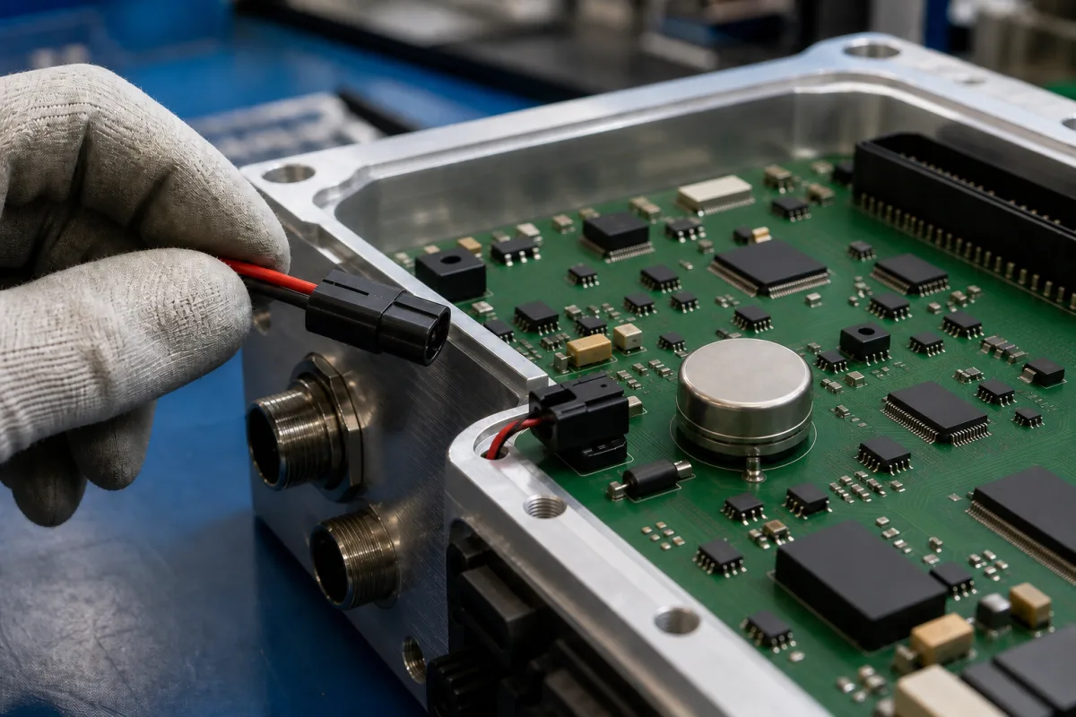
Backup Power Interface in a manufacturing environment
Representative product image. Confirm appearance and specifications with the manufacturer.

Product Specifications

Technical details and manufacturing context for Backup Power Interface

Definition
The Backup Power Interface is a critical component within Real-Time Clock systems that enables connection to auxiliary power sources (typically batteries or capacitors) to ensure continuous timekeeping and memory retention when primary power is unavailable. This interface manages power switching, voltage regulation, and isolation between main and backup power sources to prevent data loss and maintain accurate time tracking during power failures. It is designed for use in industrial computer, electronic, and optical product manufacturing applications where reliable timekeeping is essential. The interface accepts a wide input voltage range of 9–36 V DC, making it compatible with various backup sources such as lithium batteries or supercapacitors. It provides a regulated output of 3.3 V DC (±5%) to power the RTC circuitry, with an output current capability of 0.5–2 A to sustain RTC and memory functions. The switching time is less than 10 ms, ensuring no data loss during power transitions. The interface operates over a temperature range of -40 to 85 °C, with a storage range of -55 to 125 °C, and is rated for non-condensing humidity of 5–95% RH. It offers ingress protection from IP54 to IP65, providing dust and water resistance suitable for industrial environments. The dielectric strength is 500 V AC for 1 minute, and insulation resistance is at least 100 MΩ at 500 V DC, both tested according to IEC 60255-5. The connector type is a pin header or box header with a 2.54 mm pitch, and the compact dimensions are 20×15×10 mm, with a weight of 10–15 g for PCB mounting. Materials include copper alloy contacts, FR-4 PCB substrate, gold plating, and a high-temperature plastic housing. This interface is a component-level product; buyers should verify model-specific values and standards with the legal manufacturer or supplier before integration.
Working Principle
The interface monitors the main power supply voltage. When it detects a drop below the operational threshold, it automatically switches to the connected backup power source (usually a lithium battery or supercapacitor). It provides regulated voltage to the RTC circuitry while isolating the backup source from the main power circuit to prevent reverse current flow. When main power is restored, it switches back and may include charging circuitry for rechargeable backup sources.
Common Materials
Copper alloy contacts, FR-4 PCB substrate, Gold plating, High-temperature plastic housing
Technical Parameters
ParameterTypical rangeNotes & selection driver
Input Voltage Range9–36 V DCWide input for various backup sources
Output Voltage3.3 ±5% V DCFor RTC power supply
Output Current0.5–2 ASustains RTC and memory
Switching Time<10 msNo data loss during transition
Operating Temperature-40–85 °CIndustrial grade
Storage Temperature-55–125 °CExtended range for logistics
Humidity5–95 % RHNon-condensing
Ingress ProtectionIP54–IP65Dust and water resistantIEC 60529
Dielectric Strength500 V AC1 minute withstandIEC 60255-5
Insulation Resistance≥100 At 500 V DCIEC 60255-5
Connector Type2.54 mm pitchPin header or box header
Dimensions20×15×10 mmCompact footprint
Weight10–15 gLightweight for PCB mounting

Ranges are indicative industry figures for RFQ preparation, not a supplier commitment. Confirm every value and standard with the legal manufacturer before ordering.

Components / BOM
  • Power Switching Circuit
    Automatically switches between main and backup power sources based on voltage monitoring
    Material: Semiconductor components on PCB
  • Voltage Regulator
    Maintains stable voltage to RTC circuitry regardless of input source variations
    Material: Integrated circuit with passive components
  • Connector Pins Part
    Provides physical and electrical connection to backup power source
    Material: Gold-plated copper alloy
  • Isolation Diode Part
    Prevents reverse current flow from backup to main power circuit
    Material: Semiconductor diode
  • Charging Circuit Optional
    Tops up a rechargeable backup cell or supercapacitor once main power is back.

Applied To / Applications

This component is essential for the following industrial systems and equipment:

Industrial Ecosystem & Supply Chain Structure

Complementary Systems
Downstream Applications
Specialized Tooling

Application Fit & Sizing Matrix

Operational Limits
pressure: Atmospheric to 1.5 bar
other spec: Voltage Range: 2.7V to 5.5V DC, Backup Current: <5µA
temperature: -40°C to +85°C
Media Compatibility
✓ Industrial Control Systems ✓ Telecommunications Equipment ✓ Medical Monitoring Devices
Unsuitable: High-Vibration Environments (e.g., Heavy Machinery)
Sizing Data Required
  • Main Power Supply Voltage
  • RTC Module Power Consumption
  • Required Backup Duration

Reliability & Engineering Risk Analysis

Failure Mode & Root Cause
Battery Sulfation
Cause: Extended periods of low charge or inactivity leading to lead sulfate crystal formation on plates, reducing capacity and conductivity
Transfer Switch Failure
Cause: Mechanical wear, contact arcing, or control circuit malfunction preventing automatic switching between power sources during outages
Maintenance Indicators
  • Audible continuous alarm or beeping from UPS control panel indicating fault condition
  • Visible corrosion or swelling of battery cells with electrolyte leakage or case deformation
Engineering Tips
  • Implement regular load testing under simulated outage conditions to verify system response and battery capacity
  • Maintain clean, temperature-controlled environment with proper ventilation and scheduled battery impedance testing

Indicative industry ranges for design and RFQ preparation. Confirm the exact figures and applicable standard with the manufacturer before specifying.

Compliance & Manufacturing Standards

Applicable Standards
ISO 8528-1:2018 (Reciprocating internal combustion engine driven alternating current generating sets) ANSI/UL 2200 (Standard for Stationary Engine Generator Assemblies) IEC 60335-2-29 (Safety of household and similar electrical appliances - Particular requirements for battery chargers)

Quoted from the published standard.

Manufacturing Precision
  • Voltage regulation: +/- 2% of nominal output
  • Frequency stability: +/- 0.5 Hz at rated load
Quality Inspection
  • Load bank testing (verifies performance under simulated loads)
  • Dielectric withstand test (verifies electrical insulation integrity)

Manufacturers of Backup Power Interface

Manufacturer profiles associated with Backup Power Interface.

Sourcing Backup Power Interface from China?
Tell us your specification and target quantity — we will match it against manufacturer records and come back with the factories that fit.
Request manufacturers We manufacture this

Manufacturer listings support early research and capability understanding. They are not certification, ranking, or transaction guarantees.

Share this page
Technical documentation
Request current drawings, revision history, and a signed specification sheet.
Manufacturing capability
Verify equipment lists, process limits, capacity, and representative production evidence.
Inspection readiness
Confirm test methods, calibrated equipment, sampling plans, and traceable reports.
Supplier transparency
Check the legal entity, factory address, ownership, certifications, and direct contacts.

CNFX does not score or rank suppliers. Buyers must verify all claims and documents with the legal manufacturer before ordering.

Supply Chain Compatible Machinery & Devices

Industrial Smart Camera Module

The Industrial Smart Camera Module is a compact, self-contained vision processing unit designed for integration into industrial machinery and production lines.

Explore Specs →
Surface Mount Resistor

Passive electronic component for current limiting and voltage division in circuits

Explore Specs →
Surface Mount Capacitor

A surface mount capacitor is a fundamental electronic component used for energy storage, filtering, coupling, and decoupling in electronic circuits.

Explore Specs →
Surface Mount Technology (SMT) Pick-and-Place Machine

Automated machine that precisely places electronic components onto printed circuit boards.

Explore Specs →

Frequently Asked Questions

What is the purpose of the Backup Power Interface?

It maintains Real-Time Clock (RTC) functionality during main power interruptions by connecting to an auxiliary power source, ensuring continuous timekeeping and memory retention.

What are the key electrical specifications?

Input voltage range is 9–36 V DC, output voltage is 3.3 V DC ±5%, output current is 0.5–2 A, and switching time is less than 10 ms.

What environmental conditions can it withstand?

Operating temperature is -40 to 85 °C, storage temperature is -55 to 125 °C, humidity is 5–95% RH non-condensing, and ingress protection is IP54–IP65.

How should I verify compatibility with my application?

Check the connector type (2.54 mm pitch), dimensions (20×15×10 mm), and weight (10–15 g). Always confirm model-specific values and standards with the manufacturer or supplier.

Data Basis

Editorial classification, named public sources where available, and source-reviewed manufacturer records.

Preliminary Technical Classification
This page supports structured research, RFQ preparation, and supplier evaluation. It does not replace buyer-led supplier qualification, standards review, or technical approval.
Buyer enquiry

Request manufacturing insight for Backup Power Interface

Ask for use case, specification boundaries, supplier type, and RFQ preparation information for this product.

Where it goes
Straight to the CNFX editorial desk, and to the manufacturer if this product is linked to a claimed profile. Nothing is broadcast to a supplier list.
Your details stay here
We do not sell or rent enquiry data, and we do not add you to a mailing list. Used only to answer this request.
No commission, no middleman
CNFX is a directory. We take no cut of any order and never negotiate on a supplier's behalf.
What we don't claim
A listing is not an endorsement. Qualify every supplier and verify every figure yourself before ordering.

Your business information is used only to process this request.

Thank you! Your message has been sent. We'll respond within 1–3 business days.
Sorry, we couldn't send your message. Please try again, or email us at [email protected].

Need to Manufacture Backup Power Interface?

Compare manufacturer profiles with relevant product and process capability.

Previous Product
XY Positioning Stage
Last Product
Get QuotesChat