Editorial Technical Reference

CCD Detector Array

This page explains how CCD Detector Array is classified within Computer, Electronic and Optical Product Manufacturing. Technical values and manufacturer relationships are research references; confirm the current specification and supplier evidence for each order.

Technical Definition & Core Assembly

A photosensitive electronic component that converts light signals into electrical signals for detection and measurement in optical spectrometers.
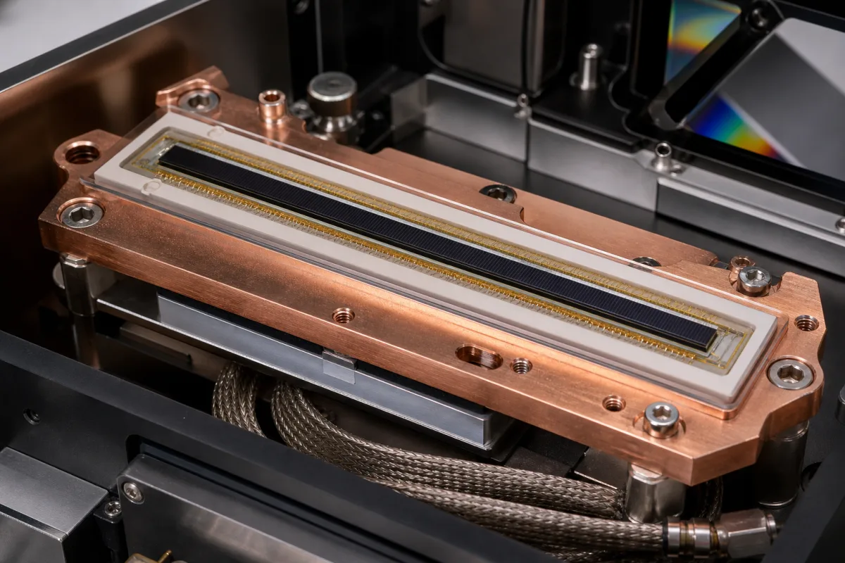
Representative product image. Confirm appearance and specifications with the manufacturer.

Product Specifications

Technical details and manufacturing context for CCD Detector Array

Definition
A CCD (Charge-Coupled Device) Detector Array is a critical component within an optical spectrometer that functions as the light detection system. It consists of multiple photosensitive pixels arranged in a linear or two-dimensional array, which captures incoming light dispersed by the spectrometer's optical elements. Each pixel generates an electrical charge proportional to the intensity of incident light, allowing for precise measurement of light intensity across different wavelengths. This enables the spectrometer to produce detailed spectral data for analysis of material composition, chemical properties, or other optical characteristics. The array is typically fabricated on silicon, with silicon dioxide and polycrystalline silicon layers, and aluminum for electrical interconnects. Key parameters include pixel array size (2048–3648 pixels), pixel size (14–24 μm), spectral response range (200–1100 nm), quantum efficiency (40–90% peak at 600 nm), dark current (0.5–10 e-/pixel/s at 25°C), readout noise (10–50 e- rms), dynamic range (1000–10000:1), full well capacity (100–500 ke-), ADC resolution (16–24 bit), maximum data rate (1–10 MHz), operating temperature (-40–85°C), cooling method (TEC or air), package type (PGA or CLCC), and weight (5–50 g). These values are typical ranges; actual specifications must be confirmed with the manufacturer for the specific model. The detector array is a component, not a complete instrument, and requires integration with other spectrometer parts. It is used in various applications, including material analysis, chemical identification, and optical characterization. For procurement, verify the exact pixel array size, spectral response, and cooling requirements against your application. Always consult the supplier for model-specific data sheets and compliance with relevant standards.
Working Principle
The CCD Detector Array operates on the principle of the photoelectric effect. When photons strike the silicon-based photosensitive surface, they generate electron-hole pairs. The resulting electrical charges are collected in potential wells at each pixel site. These charges are then sequentially transferred through the CCD structure (via clocked voltage pulses) to an output amplifier, where they are converted into voltage signals. The magnitude of these signals corresponds to the intensity of light at specific wavelength positions determined by the spectrometer's dispersion element.
Common Materials
Silicon, Silicon dioxide, Polycrystalline silicon, Aluminum
Technical Parameters
ParameterTypical rangeNotes & selection driver
Pixel Array Size2048–3648 pixelsDetermines spectral resolution and coverage
Pixel Size14–24 μmAffects sensitivity and dynamic range
Spectral Response Range200–1100 nmCovers UV to NIR
Quantum Efficiency40–90 %Peak QE at 600 nm typical
Dark Current0.5–10 e-/pixel/sAt 25°C; lower is better for low-light
Readout Noise10–50 e- rmsAffects signal-to-noise ratio
Dynamic Range1000–10000 :1Ratio of full well to noise
Full Well Capacity100–500 ke-Determines maximum signal
ADC Resolution16–24 bitHigher bits for finer intensity resolution
Maximum Data Rate1–10 MHzLimits frame rate
Operating Temperature-40–85 °CStorage temperature may differ
Cooling MethodTEC or airTEC reduces dark current
Package TypePGA or CLCCAffects mounting and thermal management
Weight5–50 gDepends on package and cooling

Ranges are indicative industry figures for RFQ preparation, not a supplier commitment. Confirm every value and standard with the legal manufacturer before ordering.

Components / BOM
  • Photosensitive Region Part
    Converts incident photons into electrical charges through the photoelectric effect
    Material: Silicon
  • Charge Transfer Structure Part
    Sequentially moves accumulated charges from pixel to pixel toward the output node
    Material: Polycrystalline silicon
  • Output Amplifier
    Converts the transferred charge packets into measurable voltage signals
    Material: Silicon
  • Protective Window Part
    Provides physical protection while allowing transmission of relevant wavelengths
    Material: Quartz or specialized glass

Applied To / Applications

This component is essential for the following industrial systems and equipment:

Industrial Ecosystem & Supply Chain Structure

Complementary Systems
Downstream Applications
Specialized Tooling

Application Fit & Sizing Matrix

Operational Limits
pressure: Atmospheric (sealed package, not pressure-rated)
other spec: Max illumination: 100 mW/cm², Dark current: <0.1 nA/cm² at 25°C
temperature: -40°C to +85°C
Media Compatibility
✓ Visible light spectrum (400-700 nm) ✓ UV-enhanced range (200-400 nm) ✓ Near-infrared (700-1100 nm) with appropriate coating
Unsuitable: High-energy radiation environments (X-ray, gamma) without shielding
Sizing Data Required
  • Spectral range required (nm)
  • Pixel resolution and array size (e.g., 2048x2048)
  • Quantum efficiency at target wavelength (%)

Reliability & Engineering Risk Analysis

Failure Mode & Root Cause
Pixel Degradation
Cause: Radiation damage from prolonged exposure to high-energy particles or UV light, leading to dark current increase and charge transfer inefficiency.
Thermal Stress Failure
Cause: Cyclic thermal expansion/contraction from inadequate temperature control, causing microcracks in silicon substrate or solder joint fatigue in readout electronics.
Maintenance Indicators
  • Increasing dark noise or hot pixel count in calibration images
  • Intermittent data dropouts or readout errors during operation
Engineering Tips
  • Implement active cooling with PID temperature control to maintain stable operating temperature (±0.5°C) and minimize thermal cycling stress
  • Use radiation-hardened shielding and implement periodic pixel calibration routines to compensate for gradual degradation effects

Indicative industry ranges for design and RFQ preparation. Confirm the exact figures and applicable standard with the manufacturer before specifying.

Compliance & Manufacturing Standards

Applicable Standards
ISO 12233:2017 (Photography - Electronic still-picture imaging - Resolution and spatial frequency responses) ANSI/IES LM-79-19 (Electrical and Photometric Measurements of Solid-State Lighting Products) DIN EN 60747-5-5 (Semiconductor devices - Discrete devices - Part 5-5: Optoelectronic devices - Photocouplers)

Quoted from the published standard.

Manufacturing Precision
  • Pixel pitch uniformity: +/- 0.5% across array
  • Quantum efficiency variation: +/- 2% at specified wavelength
Quality Inspection
  • Dark current and read noise measurement
  • Modulation Transfer Function (MTF) analysis

Manufacturers of CCD Detector Array

Manufacturer profiles associated with CCD Detector Array.

Sourcing CCD Detector Array from China?
Tell us your specification and target quantity — we will match it against manufacturer records and come back with the factories that fit.
Request manufacturers We manufacture this

Manufacturer listings support early research and capability understanding. They are not certification, ranking, or transaction guarantees.

Technical documentation
Request current drawings, revision history, and a signed specification sheet.
Manufacturing capability
Verify equipment lists, process limits, capacity, and representative production evidence.
Inspection readiness
Confirm test methods, calibrated equipment, sampling plans, and traceable reports.
Supplier transparency
Check the legal entity, factory address, ownership, certifications, and direct contacts.

CNFX does not score or rank suppliers. Buyers must verify all claims and documents with the legal manufacturer before ordering.

Supply Chain Compatible Machinery & Devices

Modular Industrial Edge Computing Device

This modular industrial edge computing device is a ruggedized system designed for deployment in harsh industrial environments to perform real-time data processing, analytics, and control functions at the network edge.

Explore Specs →
Industrial Smart Camera Module

The Industrial Smart Camera Module is a compact, self-contained vision processing unit designed for integration into industrial machinery and production lines.

Explore Specs →
Surface Mount Resistor

Passive electronic component for current limiting and voltage division in circuits

Explore Specs →
Surface Mount Capacitor

A surface mount capacitor is a fundamental electronic component used for energy storage, filtering, coupling, and decoupling in electronic circuits.

Explore Specs →

Frequently Asked Questions

What is the typical spectral response range of a CCD detector array?

The typical spectral response range is 200–1100 nm, covering ultraviolet to near-infrared. However, the exact range depends on the specific model and coating, so verify with the manufacturer.

How does cooling affect CCD performance?

Cooling reduces dark current, which is the thermal generation of electrons in the absence of light. Lower dark current improves signal-to-noise ratio, especially for low-light applications. The cooling method can be TEC (thermoelectric cooling) or air cooling, depending on the model.

What is the significance of pixel array size?

Pixel array size (e.g., 2048–3648 pixels) determines the spectral resolution and coverage of the spectrometer. A larger array can capture more wavelengths simultaneously, but the exact impact depends on the optical design.

Can I use a CCD detector array in extreme temperatures?

The operating temperature range is typically -40 to 85°C, but storage temperature may differ. For reliable operation, ensure the environment stays within the specified range and consider cooling if needed for low-light measurements.

Data Basis

Editorial classification, named public sources where available, and source-reviewed manufacturer records.

Preliminary Technical Classification
This page supports structured research, RFQ preparation, and supplier evaluation. It does not replace buyer-led supplier qualification, standards review, or technical approval.
Buyer enquiry

Request manufacturing insight for CCD Detector Array

Ask for use case, specification boundaries, supplier type, and RFQ preparation information for this product.

Where it goes
Straight to the CNFX editorial desk, and to the manufacturer if this product is linked to a claimed profile. Nothing is broadcast to a supplier list.
Your details stay here
We do not sell or rent enquiry data, and we do not add you to a mailing list. Used only to answer this request.
No commission, no middleman
CNFX is a directory. We take no cut of any order and never negotiate on a supplier's behalf.
What we don't claim
A listing is not an endorsement. Qualify every supplier and verify every figure yourself before ordering.

Your business information is used only to process this request.

Thank you! Your message has been sent. We'll respond within 1–3 business days.
Sorry, we couldn't send your message. Please try again, or email us at contact@cnfx.com.

Need to Manufacture CCD Detector Array?

Compare manufacturer profiles with relevant product and process capability.

Previous Product
XY Positioning Stage
Last Product
Get QuotesChat