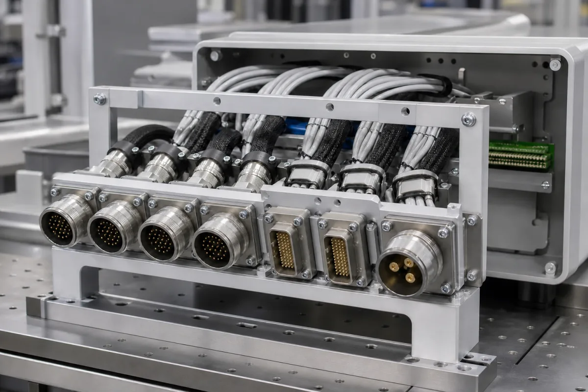
Connector assembly for an interface panel: receptacles mounted on a bulkhead plate and wired to the module
Panel-mount connector assemblies on an interface plate · jam-nut receptacles and panel thickness, keying between adjacent connectors, spare contacts, sealing and drainage, and derated current per contact size
Where cables enter a control cabinet, test rack or equipment module, the individual connectors can be built into one assembly: a machined plate carrying a group of panel-mount receptacles, each wired at the back into the module's internal harness. Buying such an assembly means deciding more than the part numbers. Adjacent receptacles must not accept each other's plugs, each insert needs spare contacts, the plate thickness must suit the receptacles' mounting, the wiring has to be sealed and drained, and every contact has to carry its current at a derated value for its size and wire.
Connector assemblies built on a panel or bulkhead plate: two or more panel-mount circular and rectangular receptacles (jam-nut, flange or wall mount) wired at the rear to the equipment's internal wiring, supplied as one unit. Free-hanging cable assemblies and wire harnesses built to drawing are covered on the Connector and cable assembly page; bare connectors sold as components, connector assembly machines and machined housings alone are outside this page.
CNFX editorial research · Sources checked October 12, 2026 · 3 sources
Laying out receptacles on the plate: keying, spare contacts, sealing and drainage
The FAA's Advisory Circular AC 43.13-1B states that mating of adjacent connectors should not be possible: adjacent connector pairs must differ in shell size, coupling means, insert arrangement or keying arrangement, and where that is impractical the wires should be routed and clamped so that wrongly mated pairs cannot reach each other; it does not recommend relying on markings or colour stripes. For spare contacts it gives as good practice two spares on connectors with 25 or fewer contacts, four on 26 to 100 and six above 100, with every cavity filled by a wired or unwired contact and unwired contacts sealed with a plastic plug. [1]
The same circular requires connectors that exclude moisture with peripheral and interfacial seals compressed on mating, a wire outside diameter matched to the rear grommet's sealing range, and installation so that fluids drain out of and not into an unmated connector; where connectors pass vertically through a shelf or floor they must be potted or environmentally sealed, with the receptacle facing downward preferred. A rear accessory backshell is required on connectors that are not enclosed, with strain-relief backshells for very small wire, frequent maintenance or high vibration. [1]
For jam-nut mounting, Glenair's D38999/23 Series III receptacle drawing calls up a panel thickness of 0.094 ± 0.032 in, with an O-ring at the panel and a recommended panel cut-out, in shell sizes 9 to 25. [3] Editorial calculation: 0.094 ± 0.032 in is about 1.6 to 3.2 mm, so a plate machined outside that band needs a spacer or a different receptacle style.
Editorial calculation with the FAA spare-contact guide: on a 37-contact insert, four spares leave 33 contacts for circuits; a 100-contact rectangular connector keeps four spares, while a 101-contact one needs six. [1]
On the drawing for the plate, give each receptacle's shell size, insert arrangement and keying or polarisation so that no two neighbours can be cross-mated, and list the spare contacts per connector.
02
Contact size, wire gauge and derated current per contact
NASA's parts instruction EEE-INST-002 derates connectors by limiting the current through each contact to the wire-derating value for the conductor size used with it; for printed circuit connectors it gives the example that a size 20 contact is derated the same as a 20 AWG wire in a bundled cable. Operating voltage is limited to 25 % of the dielectric withstanding test voltage or 75 % of the rated working voltage, whichever is lower, and temperature to the rated maximum less 25 °C. [2]
NASA bases these values on 200 °C rated wire such as PTFE-insulated wire, an ambient of 70 °C or less and a hard vacuum of 10⁻⁶ torr; it takes 80 % of them for 150 °C wire and 70 % for 135 °C wire. Its voltage example is MIL-DTL-38999 Series I, with a 1,300 V AC dielectric test voltage and a suggested 400 V AC working voltage at sea level, giving 325 V AC or 300 V AC. [2] Editorial calculation: a size 16 contact wired with 150 °C 16 AWG wire would be held to 0.8 × 6.5 = 5.2 A; a receptacle rated −65 to 200 °C, as Glenair lists for its hermetic D38999/23, would be held to 175 °C. [2][3]
The FAA circular adds that hermetic connectors and circuits with high inrush currents should be derated, and that voltage derating is required at high altitude in non-pressurised areas. [1] Editorial note: the NASA values are written for spacecraft in vacuum, where there is no convection; for a cabinet on the ground ask the supplier which derating rule its current ratings follow.
Contact size
Wire accepted by Glenair D38999/23
NASA derated current, bundled wire, at the largest gauge
Explore company information and manufacturing capabilities, then discuss the scope of your project with a relevant supplier.
Share this page
Compiled and source-reviewed by the CNFX editorial team.
Each manufacturer above links to the page on that company's own website where the product is listed, with the date we checked it. How we source and review
· Page last updated 13 October 2026
Buyer questions
How do I stop plugs going into the wrong receptacle on a panel?
FAA AC 43.13-1B asks that adjacent connectors differ in shell size, coupling means, insert arrangement or keying, and not rely on markings or colour stripes. [1]
How many spare contacts should a connector have?
As good practice, FAA AC 43.13-1B gives two spares for 25 or fewer contacts, four for 26 to 100 and six for more than 100. [1]
How much current can a size 20 contact carry when derated?
NASA EEE-INST-002 derates it to the 20 AWG bundled-wire value of 3.7 A, based on 200 °C wire at 70 °C ambient in vacuum. [2]
What panel thickness does a jam-nut 38999 receptacle need?
Glenair's D38999/23 drawing calls up 0.094 ± 0.032 in, about 1.6 to 3.2 mm. [3]
Sources and what still needs a direct check
Sources checked 2026-10-12. FAA Advisory Circular AC 43.13-1B gives aircraft connector installation practice; NASA EEE-INST-002 gives connector and wire derating for spaceflight parts; Glenair's D38999/23 drawing gives panel and wire data for one jam-nut receptacle. Ground equipment may follow other rules; ask which apply.