Editorial Technical Reference

Contact Array

This page explains how Contact Array is classified within Computer, Electronic and Optical Product Manufacturing. Technical values and manufacturer relationships are research references; confirm the current specification and supplier evidence for each order.

Technical Definition & Core Assembly

A structured arrangement of electrical contact points within a test fixture interface.
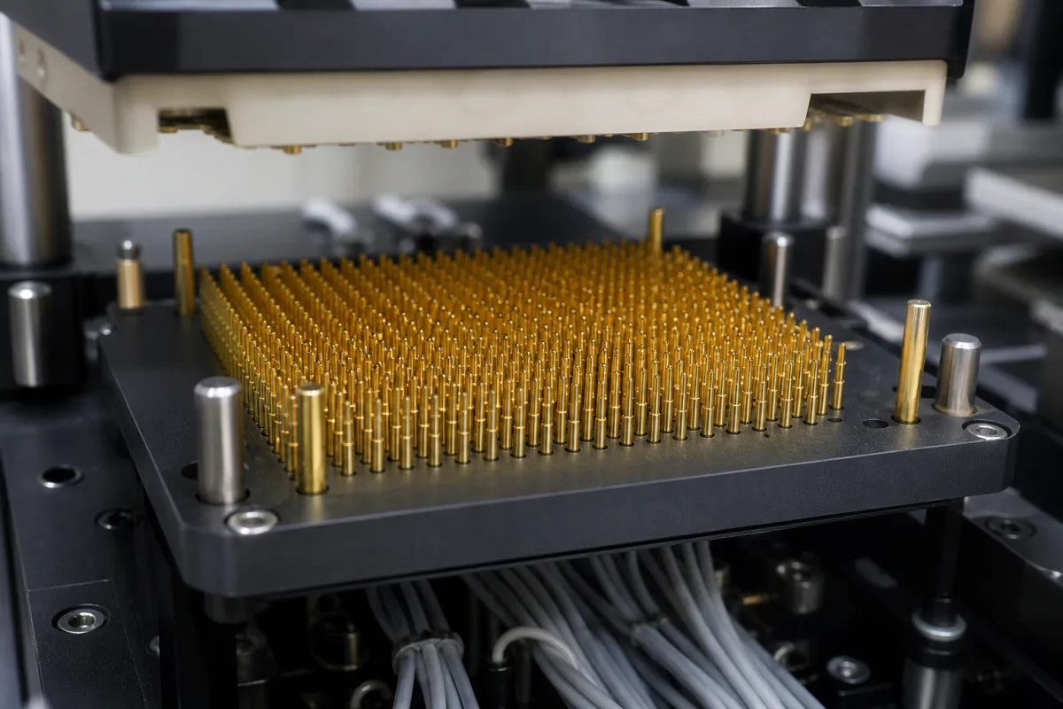
Representative product image. Confirm appearance and specifications with the manufacturer.

Product Specifications

Technical details and manufacturing context for Contact Array

Definition
A contact array is a precisely arranged set of electrical contact points or probes that form part of a test fixture interface, designed to establish reliable electrical connections with the device under test (DUT) for signal transmission, power delivery, or measurement purposes during testing procedures. The array typically consists of multiple contacts, each with a spring-loaded plunger or similar mechanism, arranged in a pattern that matches the layout of the DUT's pads, pins, or terminals. This configuration enables simultaneous testing of multiple points or channels, improving efficiency and throughput in production and validation environments. Contact arrays are commonly used in automated test equipment (ATE), burn-in test sockets, and manual test fixtures across industries such as electronics manufacturing, semiconductor testing, and telecommunications. The design of a contact array is highly customizable, with parameters such as the number of contacts, contact pitch, contact resistance, insulation resistance, dielectric withstanding voltage, current rating, operating temperature, contact material, plating, spring force, mechanical life, and operating pressure all adjustable to meet specific application requirements. For instance, the number of contacts can range from 100 to 1000, depending on the DUT's pin count, while contact pitch can vary from 0.5 mm to 2.54 mm, with finer pitches requiring precision manufacturing. Contact resistance is typically kept at or below 50 mΩ to ensure signal integrity, and insulation resistance is at least 1000 MΩ at 500 V DC to prevent leakage between contacts. Dielectric withstanding voltage ranges from 500 to 1000 V AC for one minute to prevent arcing. Current rating per contact is between 1 and 5 A, with higher currents requiring larger contacts. Operating temperature ranges from -40°C to 85°C, with extended ranges available on request. Contact material is typically beryllium copper (BeCu) per ASTM B194, with phosphor bronze as an alternative. Plating is gold over nickel, with gold thickness of 0.76 to 1.27 μm per ASTM B488, ensuring low contact resistance. Spring force per contact is 0.5 to 1.5 N, providing consistent force for reliable contact. Mechanical life is 100,000 to 500,000 cycles, dependent on spring design and material. These parameters are reference ranges and must be confirmed for the specific model and application with the legal manufacturer or supplier.
Working Principle
The contact array functions by providing multiple, aligned electrical pathways between the test equipment and the DUT. When the test fixture is engaged, each contact in the array makes physical and electrical connection with corresponding pads, pins, or terminals on the DUT, allowing for simultaneous testing of multiple points or channels. The spring-loaded contacts ensure consistent force and reliable electrical contact, accommodating slight variations in DUT surface height. This design enables efficient signal transmission, power delivery, and measurement during testing procedures.
Common Materials
Beryllium Copper, Phosphor Bronze, Gold-plated Nickel
Technical Parameters
ParameterTypical rangeNotes & selection driver
Number of Contacts100–1000 pcsCustomizable based on device under test (DUT) pin count.
Contact Pitch0.5–2.54 mmStandard pitches; finer pitches require precision manufacturing.
Contact Resistance≤50 Lower resistance ensures signal integrity.
Insulation Resistance≥1000 At 500 V DC; ensures no leakage between contacts.
Dielectric Withstanding Voltage500–1000 V ACFor 1 minute; prevents arcing.
Current Rating1–5 APer contact; higher currents require larger contacts.
Operating Temperature-40–85 °CExtended range available on request.
Contact MaterialBeCuBeryllium copper; alternative: phosphor bronze.ASTM B194
PlatingAu 0.76–1.27 μmGold over nickel; ensures low contact resistance.ASTM B488
Spring Force0.5–1.5 NPer contact; consistent force for reliable contact.
Mechanical Life100000–500000 cyclesDependent on spring design and material.
Operating Pressure1.0–1.6 MPa

Ranges are indicative industry figures for RFQ preparation, not a supplier commitment. Confirm every value and standard with the legal manufacturer before ordering.

Components / BOM
  • Contact Probe Part
    Individual electrical contact element that makes physical connection with the DUT
    Material: Beryllium Copper
  • Array Housing
    Structural frame that holds and aligns the contact probes in precise positions
    Material: Engineering Plastic or Aluminum
  • Spring Mechanism Part
    Provides consistent contact force and compensates for DUT surface variations
    Material: Stainless Steel

Applied To / Applications

This component is essential for the following industrial systems and equipment:

Industrial Ecosystem & Supply Chain Structure

Complementary Systems
Downstream Applications
Specialized Tooling

Application Fit & Sizing Matrix

Operational Limits
pressure: 0 to 50 psi
other spec: Contact force: 10-200g per pin, Insertion cycles: 10,000+
temperature: -40°C to +125°C
Media Compatibility
✓ Dry air/nitrogen purge ✓ Cleanroom environments ✓ Low-voltage DC circuits
Unsuitable: Corrosive chemical exposure or conductive particle contamination
Sizing Data Required
  • Number of contact points required
  • Pitch/spacing between contacts
  • Current/voltage per contact

Reliability & Engineering Risk Analysis

Failure Mode & Root Cause
Contact Pitting and Arcing
Cause: Electrical arcing during contact engagement/disengagement due to high inrush currents, poor contact alignment, or contamination creating localized hot spots that melt and pit the contact surfaces.
Contact Welding
Cause: Excessive current (beyond rating) or severe short-circuit events causing localized overheating that fuses mating contacts together, preventing them from opening.
Maintenance Indicators
  • Audible crackling, buzzing, or popping sounds during operation indicating arcing.
  • Visible discoloration (bluing or blackening), melting, or deformation on the contact surfaces or surrounding insulation.
Engineering Tips
  • Implement regular infrared thermography inspections to detect abnormal heating at connections before failure.
  • Establish a preventive maintenance schedule for contact cleaning (with appropriate non-residue solvents) and verification of contact pressure/alignment per manufacturer specifications.

Indicative industry ranges for design and RFQ preparation. Confirm the exact figures and applicable standard with the manufacturer before specifying.

Compliance & Manufacturing Standards

Applicable Standards
ANSI B18.3 Hexagon Socket Set Screws DIN 471 Retaining Rings for Shafts

Quoted from the published standard.

Manufacturing Precision
  • Bore diameter: +/-0.02mm
  • Flatness: 0.1mm per 100mm length
Quality Inspection
  • Dye Penetrant Test for surface defects
  • Spectrographic Analysis for material composition

Manufacturers of Contact Array

Manufacturer profiles associated with Contact Array.

Sourcing Contact Array from China?
Tell us your specification and target quantity — we will match it against manufacturer records and come back with the factories that fit.
Request manufacturers We manufacture this

Manufacturer listings support early research and capability understanding. They are not certification, ranking, or transaction guarantees.

Technical documentation
Request current drawings, revision history, and a signed specification sheet.
Manufacturing capability
Verify equipment lists, process limits, capacity, and representative production evidence.
Inspection readiness
Confirm test methods, calibrated equipment, sampling plans, and traceable reports.
Supplier transparency
Check the legal entity, factory address, ownership, certifications, and direct contacts.

CNFX does not score or rank suppliers. Buyers must verify all claims and documents with the legal manufacturer before ordering.

Supply Chain Compatible Machinery & Devices

Industrial IoT Gateway

The Industrial IoT Gateway is a ruggedized edge computing device designed for industrial environments.

Explore Specs →
Modular Industrial Edge Computing Device

This modular industrial edge computing device is a ruggedized system designed for deployment in harsh industrial environments to perform real-time data processing, analytics, and control functions at the network edge.

Explore Specs →
Industrial Smart Camera Module

The Industrial Smart Camera Module is a compact, self-contained vision processing unit designed for integration into industrial machinery and production lines.

Explore Specs →
Surface Mount Resistor

Passive electronic component for current limiting and voltage division in circuits

Explore Specs →

Frequently Asked Questions

What is a contact array used for?

A contact array is used in test fixtures to establish reliable electrical connections between test equipment and a device under test (DUT). It enables simultaneous testing of multiple points or channels for signal transmission, power delivery, or measurement during testing procedures.

What materials are commonly used for contacts?

Common contact materials include beryllium copper (BeCu) per ASTM B194 and phosphor bronze as an alternative. Contacts are typically plated with gold over nickel, with gold thickness of 0.76 to 1.27 μm per ASTM B488, to ensure low contact resistance.

What are typical electrical specifications?

Typical specifications include contact resistance ≤50 mΩ, insulation resistance ≥1000 MΩ at 500 V DC, dielectric withstanding voltage 500–1000 V AC for 1 minute, and current rating 1–5 A per contact. These are reference ranges and must be verified for the specific model.

How do I select the right contact array?

Selection depends on the DUT's pin count, pitch, current requirements, operating environment, and mechanical life expectations. Review parameters such as number of contacts, contact pitch, spring force, and operating temperature. Always confirm model-specific values with the legal manufacturer or supplier.

Data Basis

Editorial classification, named public sources where available, and source-reviewed manufacturer records.

Preliminary Technical Classification
This page supports structured research, RFQ preparation, and supplier evaluation. It does not replace buyer-led supplier qualification, standards review, or technical approval.
Buyer enquiry

Request manufacturing insight for Contact Array

Ask for use case, specification boundaries, supplier type, and RFQ preparation information for this product.

Where it goes
Straight to the CNFX editorial desk, and to the manufacturer if this product is linked to a claimed profile. Nothing is broadcast to a supplier list.
Your details stay here
We do not sell or rent enquiry data, and we do not add you to a mailing list. Used only to answer this request.
No commission, no middleman
CNFX is a directory. We take no cut of any order and never negotiate on a supplier's behalf.
What we don't claim
A listing is not an endorsement. Qualify every supplier and verify every figure yourself before ordering.

Your business information is used only to process this request.

Thank you! Your message has been sent. We'll respond within 1–3 business days.
Sorry, we couldn't send your message. Please try again, or email us at contact@cnfx.com.

Need to Manufacture Contact Array?

Compare manufacturer profiles with relevant product and process capability.

Previous Product
XY Positioning Stage
Last Product
Get QuotesChat