Editorial Technical Reference

Control Processing Unit

This page explains how Control Processing Unit is classified within Computer, Electronic and Optical Product Manufacturing. Technical values and manufacturer relationships are research references; confirm the current specification and supplier evidence for each order.

Technical Definition & Core Assembly

A specialized electronic component that processes control signals and executes computational tasks within the Alignment Assistance System.
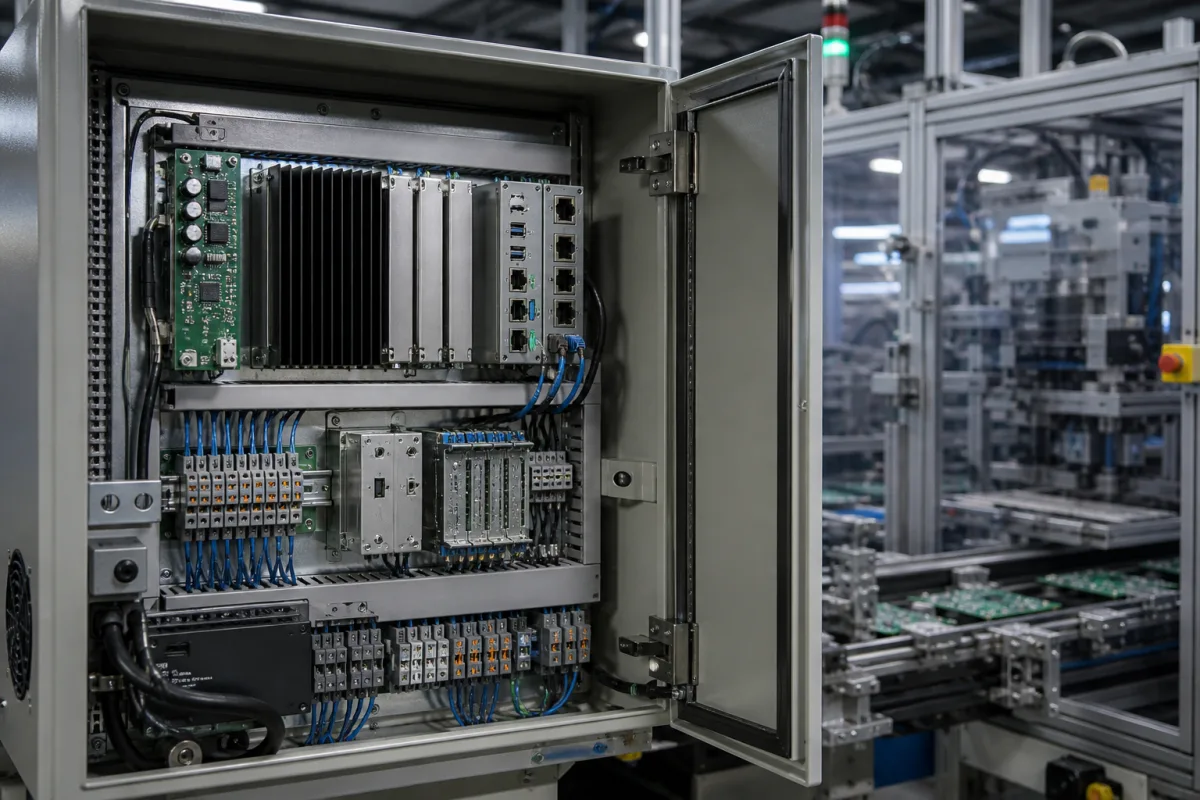
Representative product image. Confirm appearance and specifications with the manufacturer.

Product Specifications

Technical details and manufacturing context for Control Processing Unit

Definition
The Control Processing Unit is the computational core of the Alignment Assistance System. It receives sensor data from position, orientation, and force sensors, executes alignment algorithms, and generates control signals for actuators. The unit manages system coordination to ensure precise positioning and orientation adjustments. It is designed for industrial environments, with a supply voltage of 24 V DC ±10%, power consumption up to 15 W, and an operating temperature range of -40 to 85 °C. The processor clock speed ranges from 400 to 800 MHz, with RAM capacity between 512 and 1024 MB and flash storage of 4 to 8 GB. Signal processing delay is kept at or below 10 ms for real-time feedback. The unit provides 8 to 16 analog input channels and 16 to 32 digital I/O lines, configurable as inputs or outputs. Communication interfaces include CAN 2.0B and RS-485, per ISO 11898. The compact form factor measures 100 x 60 x 25 mm and weighs no more than 200 g. Ingress protection is rated IP54 to IP65 per IEC 60529, and relative humidity tolerance is 5% to 95% non-condensing. The unit is constructed with semiconductor silicon, copper, and epoxy resin. It is intended for integration into alignment systems, and all specifications are reference ranges that must be verified with the legal manufacturer or supplier for the specific model and application.
Working Principle
The unit operates by receiving input signals from various sensors (position, orientation, force). It processes this data through embedded algorithms to calculate required adjustments. It then outputs control signals to drive motors, actuators, or other positioning mechanisms to achieve the desired alignment. The processor clock speed and RAM capacity are sufficient for real-time control algorithms. Signal processing delay is critical for real-time alignment feedback and is maintained at or below 10 ms. The unit's communication interfaces allow integration with the alignment system. The analog input channels and digital I/O lines provide flexibility for sensor and actuator connections. The unit's operating temperature and humidity ranges define its environmental limits; outside these ranges, performance may degrade or the processor may reset or malfunction.
Common Materials
Semiconductor silicon, Copper, Epoxy resin
Technical Parameters
ParameterTypical rangeNotes & selection driver
Supply Voltage24 ±10% V DCOutside this range the processor may reset or malfunction.
Power Consumption≤15 WMaximum power draw under full load.
Operating Temperature-40–85 °CExtended exposure beyond this range may degrade performance.
Storage Temperature-55–95 °CNon-operating storage condition.
Relative Humidity5–95 %Non-condensing.
Ingress ProtectionIP54–IP65IP65 for dust-tight and water-jet protection.IEC 60529
Processor Clock Speed400–800 MHzHigher clock speed improves response time.
RAM Capacity512–1024 MBSufficient for real-time control algorithms.
Flash Storage4–8 GBFor firmware and data logging.
Signal Processing Delay≤10 msCritical for real-time alignment feedback.
Analog Input Channels8–16Number of channels for sensor inputs.
Digital I/O Lines16–32Configurable as inputs or outputs.
Communication InterfaceCAN 2.0B, RS-485For integration with alignment system.ISO 11898
Dimensions (W x H x D)100 x 60 x 25 mmCompact form factor for space-constrained installations.
Weight≤200 gLightweight for easy mounting.

Ranges are indicative industry figures for RFQ preparation, not a supplier commitment. Confirm every value and standard with the legal manufacturer before ordering.

Components / BOM

Applied To / Applications

This component is essential for the following industrial systems and equipment:

Industrial Ecosystem & Supply Chain Structure

Complementary Systems
Downstream Applications
Specialized Tooling

Application Fit & Sizing Matrix

Operational Limits
pressure: 0 to 1 bar (ambient pressure only)
other spec: Max computational load: 100 MIPS, Power supply: 24VDC ±10%, Humidity: 0-95% non-condensing
temperature: -40°C to +85°C
Media Compatibility
✓ Clean dry air environments ✓ Industrial control cabinets ✓ Electronics enclosures with IP54+ protection
Unsuitable: Direct exposure to corrosive chemicals or conductive fluids
Sizing Data Required
  • Required processing speed (MIPS)
  • Number of simultaneous control loops
  • Communication protocol requirements (e.g., Modbus, Profibus, Ethernet/IP)

Reliability & Engineering Risk Analysis

Failure Mode & Root Cause
Thermal throttling and overheating
Cause: Inadequate cooling system performance due to dust accumulation on heatsinks, degraded thermal paste, or fan failure, leading to sustained high temperatures beyond design limits.
Electromigration and solder joint fatigue
Cause: Cyclic thermal expansion and contraction from power cycling or environmental temperature fluctuations, causing microscopic cracks in solder balls and interconnects over time.
Maintenance Indicators
  • Audible: Unusual high-pitched coil whine or grinding fan noises indicating bearing wear or electrical stress
  • Visual: System instability, frequent blue screens, or performance degradation under load, often accompanied by elevated temperature readings in monitoring software
Engineering Tips
  • Implement proactive thermal management: Regularly clean cooling components, replace thermal paste annually, and ensure adequate airflow in the enclosure to maintain operating temperatures 15-20°C below maximum rated limits.
  • Utilize controlled power cycling: Avoid frequent hard shutdowns; instead use graceful shutdown procedures and maintain stable power supply with UPS protection to minimize thermal cycling stress on solder joints.

Indicative industry ranges for design and RFQ preparation. Confirm the exact figures and applicable standard with the manufacturer before specifying.

Compliance & Manufacturing Standards

Applicable Standards
ANSI/ISA-95.00.01 Enterprise-Control System Integration CE Marking (EU Directive 2014/35/EU Low Voltage Directive)

Quoted from the published standard.

Manufacturing Precision
  • Thermal Interface Flatness: ≤0.05mm
  • Pin Alignment: ±0.1mm
Quality Inspection
  • Thermal Cycling Test (-40°C to +125°C, 1000 cycles)
  • Functional Electrical Test (Fully Automated Test Equipment)

Manufacturers of Control Processing Unit

Manufacturer profiles associated with Control Processing Unit.

Sourcing Control Processing Unit from China?
Tell us your specification and target quantity — we will match it against manufacturer records and come back with the factories that fit.
Request manufacturers We manufacture this

Manufacturer listings support early research and capability understanding. They are not certification, ranking, or transaction guarantees.

Technical documentation
Request current drawings, revision history, and a signed specification sheet.
Manufacturing capability
Verify equipment lists, process limits, capacity, and representative production evidence.
Inspection readiness
Confirm test methods, calibrated equipment, sampling plans, and traceable reports.
Supplier transparency
Check the legal entity, factory address, ownership, certifications, and direct contacts.

CNFX does not score or rank suppliers. Buyers must verify all claims and documents with the legal manufacturer before ordering.

Supply Chain Compatible Machinery & Devices

Industrial Smart Camera Module

The Industrial Smart Camera Module is a compact, self-contained vision processing unit designed for integration into industrial machinery and production lines.

Explore Specs →
Surface Mount Resistor

Passive electronic component for current limiting and voltage division in circuits

Explore Specs →
Surface Mount Capacitor

A surface mount capacitor is a fundamental electronic component used for energy storage, filtering, coupling, and decoupling in electronic circuits.

Explore Specs →
Surface Mount Technology (SMT) Pick-and-Place Machine

Automated machine that precisely places electronic components onto printed circuit boards.

Explore Specs →

Frequently Asked Questions

What is the supply voltage range for the Control Processing Unit?

The supply voltage is 24 V DC with a tolerance of ±10%, meaning the unit should operate within 21.6 V to 26.4 V DC. Outside this range, the processor may reset or malfunction. Always verify the exact requirements with the manufacturer for your specific model.

What communication interfaces does the unit support?

The unit supports CAN 2.0B and RS-485 interfaces, referenced to ISO 11898. These are used for integration with the alignment system. Confirm the exact interface configuration and protocol details with the supplier for your application.

What are the environmental limits for operation and storage?

The operating temperature range is -40 to 85 °C, and storage temperature is -55 to 95 °C. Relative humidity must be kept between 5% and 95% non-condensing. Extended exposure beyond these ranges may degrade performance. The ingress protection rating is IP54 to IP65 per IEC 60529, indicating dust-tight and water-jet protection at the higher rating.

How many input/output channels are available?

The unit provides 8 to 16 analog input channels and 16 to 32 digital I/O lines, which are configurable as inputs or outputs. The exact number and configuration depend on the specific model. Check the technical documentation from the manufacturer for your unit.

Data Basis

Editorial classification, named public sources where available, and source-reviewed manufacturer records.

Preliminary Technical Classification
This page supports structured research, RFQ preparation, and supplier evaluation. It does not replace buyer-led supplier qualification, standards review, or technical approval.
Buyer enquiry

Request manufacturing insight for Control Processing Unit

Ask for use case, specification boundaries, supplier type, and RFQ preparation information for this product.

Where it goes
Straight to the CNFX editorial desk, and to the manufacturer if this product is linked to a claimed profile. Nothing is broadcast to a supplier list.
Your details stay here
We do not sell or rent enquiry data, and we do not add you to a mailing list. Used only to answer this request.
No commission, no middleman
CNFX is a directory. We take no cut of any order and never negotiate on a supplier's behalf.
What we don't claim
A listing is not an endorsement. Qualify every supplier and verify every figure yourself before ordering.

Your business information is used only to process this request.

Thank you! Your message has been sent. We'll respond within 1–3 business days.
Sorry, we couldn't send your message. Please try again, or email us at contact@cnfx.com.

Need to Manufacture Control Processing Unit?

Compare manufacturer profiles with relevant product and process capability.

Previous Product
XY Positioning Stage
Last Product
Get QuotesChat