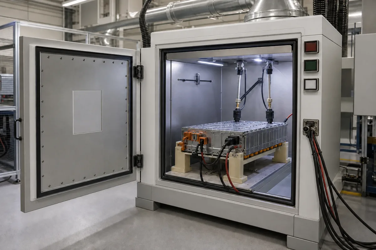
Electrical testing chamber for lithium-ion modules: the protective enclosure for charge, discharge, overcharge and short-circuit tests, specified by the EUCAR hazard level it can contain
Protective enclosures for charging, discharging, overcharge and short-circuit tests on lithium-ion cells and modules · EUCAR hazard levels 0 to 7, what each safety package adds, and the electrical abuse test conditions it must contain
When a lithium-ion module is connected to a cycler, the test itself can go wrong: overcharge, an external short or a cell defect can make the device vent, burn or rupture. An electrical testing chamber is the enclosure that holds the device under test while power and sense leads pass in from outside, and that keeps the consequences inside. Its specification starts not with temperature range but with the worst outcome the test is allowed to reach on the EUCAR hazard scale, because that decides the relief openings, gas sensors, inerting, extinguishing and door locking that must be fitted. The picture shows such a unit: a module on insulating supports below two spring-loaded contact probes, power cables entering through a side port, an exhaust duct on the roof and red, green and white indicator lamps beside a heavy riveted door.
Enclosures and test chambers that contain lithium-ion cells, modules and small packs during electrical tests (charge and discharge cycling, overcharge, external short circuit, forced discharge), with their EUCAR hazard-level rating, pressure relief, gas detection, inerting and extinguishing, door locking and cable or probe feed-throughs. Climatic, thermal shock and stability chambers chosen for their temperature and humidity performance are covered on the Test chamber page; powered burn-in racks for computer boards on the Motherboard burn-in rack page; vacuum outgassing chambers on the Outgassing test sample chamber page; EV pack housings on the Battery enclosures page. Crush, nail-penetration and drop rigs, and walk-in bunkers for full vehicle packs, are outside this page.
CNFX editorial research · Sources checked October 13, 2026 · 4 sources
From Level 0 to Level 7: the EUCAR outcome scale that sets how much the chamber must withstand
Sandia's battery abuse manual for the United States Advanced Battery Consortium scores every abuse response on the EUCAR hazard severity scale, adapted from SAND2005-3123 and SAE J2464. [1] The chamber has to be built for the highest level the planned tests can reach.
The wording differs between publishers. BINDER describes Level 6 as “No explosion, but flying parts of the active mass”, while the USABC manual describes Level 6 as disintegration without flying parts of high thermal or kinetic energy; BINDER also names Level 1 “Passive protection activated”. [2][1] A chamber offer that cites a level should state which definition it was designed against.
WKM points out that fire needs an ignition source, a combustible substance and oxygen together, and that once escaping electrolyte or gas is combustible and an ignition source is present, Level 3 or 4 becomes Level 5. Its example is dimethyl carbonate, an electrolyte solvent with a flash point of +16 °C, whose vapour from a leak can be ignited by a hot surface such as the chamber's own electric heaters; without further measures the leak must not be able to exceed 50 % of the lower explosive limit. [4] WKM recommends that a chamber where Level 7 is possible be installed in a separate locked room with no personnel access during the test and its own exhaust system. [4]
No explosion; the device could disintegrate slowly without flying parts of high thermal or kinetic energy [1]
7
Explosion
Disintegration with externally damaging thermal and kinetic forces [1]
Before asking for prices, decide with your risk assessment the highest EUCAR level each planned test can reach, and whether the electrolyte or vent gas is combustible.
02
Relief flaps, rupture discs, H₂/CO/O₂ sensors and inert gas: what each hazard level adds to the enclosure
Chamber makers sell the safety equipment as packages keyed to hazard levels. BINDER and WKM publish theirs; the level boundaries do not match exactly.
BINDER states that Package S is used to test charging and discharging currents at constant or dynamic temperatures, and that its chambers have reversible stainless-steel pressure relief flaps and an enhanced door-locking mechanism. [2] WKM's optional equipment includes a rupture diaphragm with increased pressure resistance of the chamber, a safety temperature limiter with a release contact for test-material control, and a Storz coupling for extinguishing water. [4]
Editorial calculation: BINDER's Ø150 mm flap opens about 177 cm² (π × 7.5²) and its Ø250 mm duct connection about 491 cm² (π × 12.5²), so the duct has roughly 2.8 times the flap's area; the optional Ø200 mm flap gives about 314 cm². [3]
Package
Hazard levels
Safety equipment listed
BINDER Package A
0 to 2 (ageing of unpowered devices)
Class 2 independent temperature limiter preset to 120 °C; range −70 to +120 °C [3]
BINDER Package P
Up to 4 (ageing and performance tests)
Two reinforced door latches; reversible pressure relief flap Ø150 mm with Ø250 mm connection; non-controlled inert gas connection; option 200 mm overpressure flap [3]
BINDER Package P+ / G
Up to 5
Adds independent temperature detection that triggers CO₂ cooling and flushing at 120 °C, manual CO₂ trigger, alarms; Package G adds a CO sensor that triggers CO₂ flushing; range −70 to +110 °C [3]
BINDER Package S
Level 6
H₂, CO and O₂ sensors that trigger CO₂ flushing; controlled inerting; electromechanical door lock; relief flap Ø150 mm [3]
List the sensors, their trigger actions, the relief area and burst pressure, the inerting gas and how it is supplied, and the release contact that cuts power to the device under test.
03
Overcharge to 200 % SOC, 10 mΩ external shorts and 7.2 kW module charging: the electrical abuse the chamber has to hold
The tests run inside the chamber decide how much energy can be released and for how long the chamber stays closed afterwards.
The USABC manual's primary overcharge rate is 1C, with 4C and 7.2 kW constant-power charging as secondary rates; 7.2 kW is intended for modules and packs and represents a level 2 charging station. The test ends at 200 % SOC, with a cell voltage limit of 20 V and a pack limit of 1.5 × pack voltage. [1] For external short circuit it uses a 10 mΩ (±5 %) load for devices below 5 mΩ internal resistance or of unknown resistance, reached in under 1 second and held for 60 minutes; the load includes contact and cable resistance, and module or pack failures have been observed with the short applied for more than 120 minutes. [1]
After each of these tests the device should be monitored for at least 30 minutes, and an event of EUCAR 5 or above causes significant destruction of the battery. [1] The manual lists local exhaust ventilation for toxic gases, real-time monitoring and lock-out/tag-out of electrical equipment among engineering controls. [1]
Editorial calculation: at 7.2 kW and an example module voltage of 400 V (an example value, not from the manual), the charging current would be 18 A (7,200 ÷ 400); at an example 48 V it would be 150 A. The cable feed-throughs and contact probes in the enclosure must carry that current, and in a short-circuit test their resistance counts towards the 10 mΩ load. [1]
Give the cycler's voltage and current range, the abuse tests planned, the post-test hold time, and how leads and sense wires pass through the chamber wall.
04
Data for a battery electrical test chamber enquiry
Paste it into your enquiry below or into an email to a maker, then replace every bracket.
Device under test: [cell/module/pack; chemistry; Wh; dimensions]
Tests: [cycling; overcharge; external short; forced discharge]
Highest EUCAR level expected: [0–7]
Temperature range during tests: [°C]
Gas detection: [H₂; CO; O₂; others; trigger actions]
Pressure relief: [flap size; rupture disc; duct connection]
Inerting and extinguishing: [N₂; CO₂; water mist; supply]
Feed-throughs: [current; voltage; number of sense lines]
Interlocks: [door lock; release contact to cycler; emergency stop]
Explore company information and manufacturing capabilities, then discuss the scope of your project with a relevant supplier.
Share this page
Compiled and source-reviewed by the CNFX editorial team.
Each manufacturer above links to the page on that company's own website where the product is listed, with the date we checked it. How we source and review
· Page last updated 13 October 2026
Buyer questions
What is a EUCAR hazard level?
A 0 to 7 scale for the outcome of a battery test, from no effect (0) through leakage (3), venting (4), fire (5) and rupture (6) to explosion (7); Sandia's USABC manual uses it to score abuse tests. [1]
What does a Level 6 battery chamber include?
BINDER's Level 6 package lists H₂, CO and O₂ sensors that trigger CO₂ flushing, controlled inerting, a Ø150 mm pressure relief flap and an electromechanical door lock; WKM's Package IV lists rupture discs, permanent nitrogen inerting and O₂ measurement. [3][4]
How long is an external short-circuit test held?
The USABC manual applies a 10 mΩ load for 60 minutes and notes that module and pack failures have been seen with shorts held over 120 minutes. [1]
Can a leak of electrolyte become a fire inside the chamber?
WKM notes that dimethyl carbonate has a flash point of +16 °C and its vapour can be ignited by hot surfaces such as heaters, so Level 3 or 4 becomes Level 5 when the escaping medium is combustible. [4]
Sources and what still needs a direct check
Sources checked 2026-10-13. Four documents from three publishers: the USABC battery abuse testing manual prepared by Sandia National Laboratories (2022), BINDER's EUCAR hazard-level article and battery test chamber package page, and WKM's explanation of EUCAR hazard levels and its chamber packages.