Editorial Technical Reference

Safety Interlock System

This page explains how Safety Interlock System is classified within Electrical Equipment Manufacturing. Technical values and manufacturer relationships are research references; confirm the current specification and supplier evidence for each order.

Technical Definition & Core Assembly

A safety-critical control system that prevents hazardous operation of dielectric strength testers by ensuring proper sequencing and conditions.
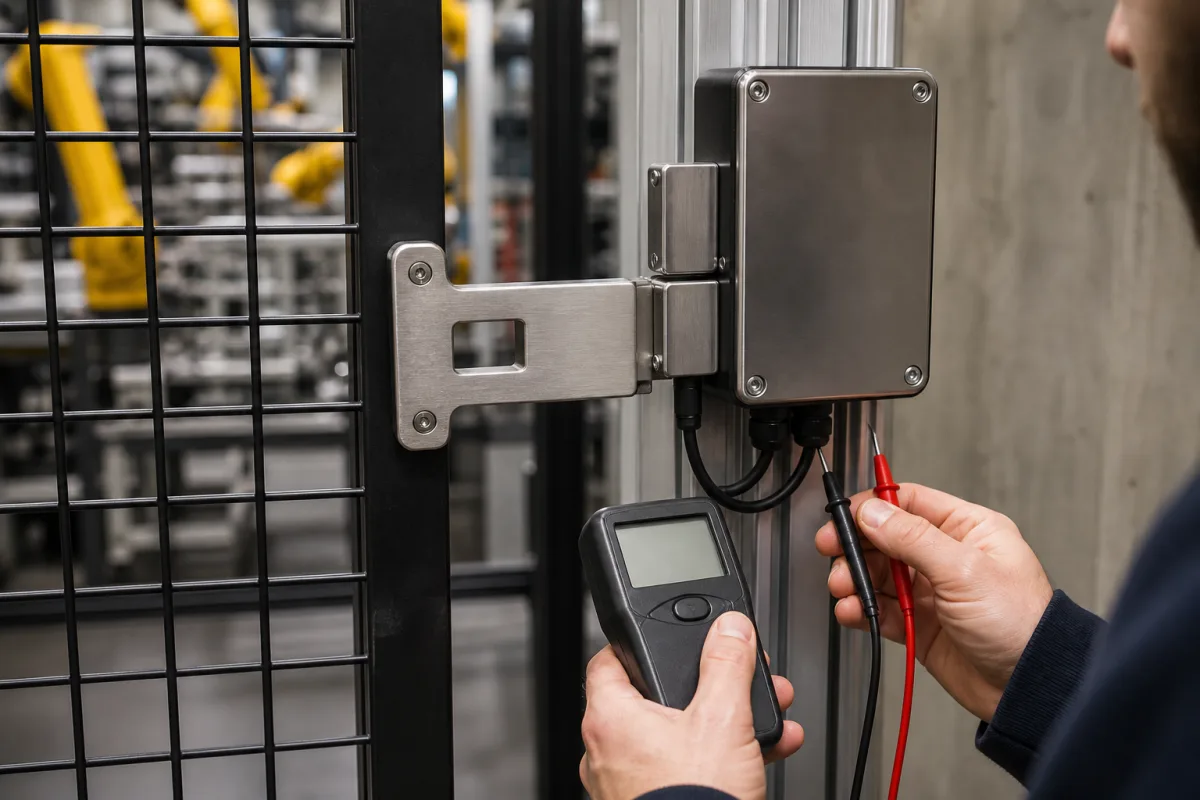
Representative product image. Confirm appearance and specifications with the manufacturer.

Product Specifications

Technical details and manufacturing context for Safety Interlock System

Definition
A safety interlock system in an Industrial Dielectric Strength Tester is an integrated safety mechanism that prevents the application of high-voltage test signals unless all safety conditions are met. It ensures operators cannot access test areas during active testing, verifies proper grounding and shielding, monitors door/cover positions, and prevents accidental energization. This system is essential for protecting personnel from electrical hazards during insulation testing procedures. The system uses sensors (limit switches, proximity sensors, safety relays) to monitor safety-critical conditions such as enclosure doors, grounding connections, and operator presence. When any safety condition is violated, the interlock immediately cuts power to the high-voltage circuit and prevents test initiation. Some systems use dual-channel redundant circuits with self-checking capabilities to ensure fail-safe operation even with component failures. The interlock system is designed to comply with relevant safety standards, including IEC 61010-1, IEC 60204-1, and IEC 60947-5-1, which are referenced for verification. Key parameters include a rated voltage of 220–240 V AC, rated frequency of 50–60 Hz, power consumption ≤15 W, response time ≤100 ms, contact rating 5–250 V AC/DC (max 5 A resistive), mechanical life ≥1,000,000 cycles, electrical life ≥100,000 cycles, operating temperature -10–55 °C, storage temperature -25–70 °C, relative humidity 20–85% RH, degree of protection IP54–IP65, insulation resistance ≥100 MΩ at 500 V DC, dielectric strength 2–4 kV, and weight 0.5–2.0 kg. Materials include stainless steel, engineering plastics, copper contacts, and electronic components. These values are reference ranges and must be confirmed for the specific model and application with the legal manufacturer or supplier. The system is a component of the dielectric strength tester and is not a standalone product. For selection, verify the interlock's compatibility with the tester's control logic, safety circuit architecture, and environmental conditions. During maintenance, check sensor operation, contact wear, and wiring integrity. Failure boundaries include loss of sensor function, relay welding, or power supply failure; the fail-safe design should ensure safe state. Always consult the manufacturer's documentation for installation, commissioning, and periodic testing requirements.
Working Principle
The system uses sensors (limit switches, proximity sensors, safety relays) to monitor safety-critical conditions such as enclosure doors, grounding connections, and operator presence. When any safety condition is violated, the interlock immediately cuts power to the high-voltage circuit and prevents test initiation. Some systems use dual-channel redundant circuits with self-checking capabilities to ensure fail-safe operation even with component failures.
Common Materials
Stainless steel, Engineering plastics, Copper contacts, Electronic components
Technical Parameters
ParameterTypical rangeNotes & selection driver
Rated Voltage220–240 V ACMains supply for control logicIEC 61010-1
Rated Frequency50–60 HzAuto-detectedIEC 61010-1
Power Consumption≤15 WExcluding external loads
Response Time≤100 msFrom interlock trigger to contact openIEC 60204-1
Contact Rating5–250 V AC/DCMax 5 A resistiveIEC 60947-5-1
Mechanical Life≥1,000,000 cyclesAt rated loadIEC 60947-5-1
Electrical Life≥100,000 cyclesAt rated loadIEC 60947-5-1
Operating Temperature-10–55 °CNon-condensingIEC 60068-2-1/2
Storage Temperature-25–70 °CNon-condensingIEC 60068-2-1/2
Relative Humidity20–85 % RHNon-condensingIEC 60068-2-78
Degree of ProtectionIP54–IP65Enclosure ratingIEC 60529
Insulation Resistance≥100 At 500 V DCIEC 60255-5
Dielectric Strength2–4 kVBetween live parts and enclosureIEC 61010-1
Weight0.5–2.0 kgDepending on configuration

Ranges are indicative industry figures for RFQ preparation, not a supplier commitment. Confirm every value and standard with the legal manufacturer before ordering.

Components / BOM
  • Safety Relay Module
    Monitors safety inputs and controls power to high-voltage circuit
    Material: Plastic housing with metal contacts
  • Door Interlock Switch
    Detects when test chamber doors are properly closed and locked
    Material: Stainless steel with microswitch
  • Emergency Stop Button
    Provides manual override to immediately cut power in emergencies
    Material: Plastic with metal contacts
  • Grounding Verification Sensor
    Confirms proper grounding of test specimen before allowing high voltage
    Material: Copper contacts with sensing electronics

Applied To / Applications

This component is essential for the following industrial systems and equipment:

Industrial Ecosystem & Supply Chain Structure

Complementary Systems
Downstream Applications
Specialized Tooling

Application Fit & Sizing Matrix

Operational Limits
pressure: 0 to 1 bar (atmospheric)
other spec: Dielectric test voltage range: 0-100 kV, Interlock response time: <100 ms
temperature: -20°C to +70°C
Media Compatibility
✓ Clean dry air ✓ Non-conductive dielectric fluids ✓ Standard industrial control voltages (24VDC/110VAC)
Unsuitable: Corrosive or conductive atmospheres (e.g., salt spray, conductive dust)
Sizing Data Required
  • Maximum dielectric test voltage (kV)
  • Required safety integrity level (SIL rating)
  • Number of interlock points and sequencing complexity

Reliability & Engineering Risk Analysis

Failure Mode & Root Cause
Sensor failure or drift
Cause: Environmental contamination (dust, moisture, chemicals), mechanical wear, or electrical degradation leading to inaccurate readings or complete loss of signal.
Relay or contactor failure
Cause: Arcing, contact welding, coil burnout, or mechanical sticking due to excessive cycling, voltage spikes, or inadequate maintenance.
Maintenance Indicators
  • Intermittent or false tripping of the safety interlock without an actual hazard present
  • Audible buzzing or chattering from relays/contactors, or visible signs of overheating (discoloration, melting) on components
Engineering Tips
  • Implement regular functional testing and calibration of sensors and logic solvers per manufacturer specifications and safety standards (e.g., IEC 61511) to ensure integrity.
  • Use sealed or appropriately rated components for the environment, maintain clean electrical connections, and install surge protection to prevent electrical damage.

Indicative industry ranges for design and RFQ preparation. Confirm the exact figures and applicable standard with the manufacturer before specifying.

Compliance & Manufacturing Standards

Applicable Standards
ISO 13849-1: Safety of machinery - Safety-related parts of control systems ANSI B11.19: Performance Requirements for Safeguarding CE Marking (Machinery Directive 2006/42/EC): Essential health and safety requirements

Quoted from the published standard.

Manufacturing Precision
  • Switch Actuation Force: +/- 0.5 N
  • Electrical Contact Resistance: +/- 10 mΩ
Quality Inspection
  • Functional Safety Test (PL/SIL verification)
  • Dielectric Strength Test (High-potential test)

Manufacturers of Safety Interlock System

Manufacturer profiles associated with Safety Interlock System.

Sourcing Safety Interlock System from China?
Tell us your specification and target quantity — we will match it against manufacturer records and come back with the factories that fit.
Request manufacturers We manufacture this

Manufacturer listings support early research and capability understanding. They are not certification, ranking, or transaction guarantees.

Technical documentation
Request current drawings, revision history, and a signed specification sheet.
Manufacturing capability
Verify equipment lists, process limits, capacity, and representative production evidence.
Inspection readiness
Confirm test methods, calibrated equipment, sampling plans, and traceable reports.
Supplier transparency
Check the legal entity, factory address, ownership, certifications, and direct contacts.

CNFX does not score or rank suppliers. Buyers must verify all claims and documents with the legal manufacturer before ordering.

Supply Chain Compatible Machinery & Devices

Circuit Breaker Arc Chute

The Circuit Breaker Arc Chute is a critical safety component in electrical circuit breakers, designed to rapidly extinguish electric arcs that form during circuit interruption.

Explore Specs →
Medium Voltage Switchgear Assembly Line

Automated production system for assembling medium voltage electrical switchgear.

Explore Specs →
Motor Terminal Block

A motor terminal block is a standardized electrical component that provides secure, insulated connection points for motor winding leads.

Explore Specs →
PLC Control System

A digital industrial computer control system that monitors inputs, makes decisions based on a custom program, and controls outputs to automate industrial processes.

Explore Specs →

Frequently Asked Questions

What is the purpose of a safety interlock system in a dielectric strength tester?

The safety interlock system prevents the application of high-voltage test signals unless all safety conditions are met, such as proper enclosure closure, grounding, and operator presence. It cuts power to the high-voltage circuit if any condition is violated, protecting personnel from electrical hazards.

What standards are referenced for this safety interlock system?

The system references standards such as IEC 61010-1, IEC 60204-1, and IEC 60947-5-1 for safety, response time, and contact ratings. These are verification references; actual compliance must be confirmed with the manufacturer.

What are the typical response time and contact ratings?

The response time from interlock trigger to contact open is ≤100 ms. The contact rating is 5–250 V AC/DC, with a maximum resistive load of 5 A. These are reference values and should be verified for the specific model.

How should the safety interlock system be maintained?

Regular maintenance should include checking sensor operation, contact wear, wiring integrity, and verifying that the fail-safe function works. Follow the manufacturer's instructions for periodic testing and replacement of worn components.

Data Basis

Editorial classification, named public sources where available, and source-reviewed manufacturer records.

Preliminary Technical Classification
This page supports structured research, RFQ preparation, and supplier evaluation. It does not replace buyer-led supplier qualification, standards review, or technical approval.
Buyer enquiry

Request manufacturing insight for Safety Interlock System

Ask for use case, specification boundaries, supplier type, and RFQ preparation information for this product.

Where it goes
Straight to the CNFX editorial desk, and to the manufacturer if this product is linked to a claimed profile. Nothing is broadcast to a supplier list.
Your details stay here
We do not sell or rent enquiry data, and we do not add you to a mailing list. Used only to answer this request.
No commission, no middleman
CNFX is a directory. We take no cut of any order and never negotiate on a supplier's behalf.
What we don't claim
A listing is not an endorsement. Qualify every supplier and verify every figure yourself before ordering.

Your business information is used only to process this request.

Thank you! Your message has been sent. We'll respond within 1–3 business days.
Sorry, we couldn't send your message. Please try again, or email us at contact@cnfx.com.

Need to Manufacture Safety Interlock System?

Compare manufacturer profiles with relevant product and process capability.

Previous Product
Wire Tensioning System
Last Product
Get QuotesChat