Editorial Technical Reference

Feedback Input Circuit

This page explains how Feedback Input Circuit is classified within Computer, Electronic and Optical Product Manufacturing. Technical values and manufacturer relationships are research references; confirm the current specification and supplier evidence for each order.

Technical Definition & Core Assembly

Electronic circuit that receives and processes feedback signals from sensors in an axis control system
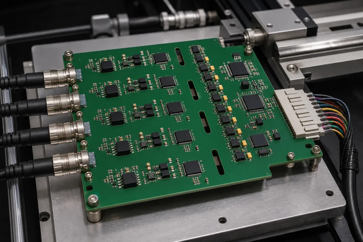
Representative product image. Confirm appearance and specifications with the manufacturer.

Product Specifications

Technical details and manufacturing context for Feedback Input Circuit

Definition
The Feedback Input Circuit is a specialized electronic component within an Axis Control Module. Its primary function is to receive, condition, and process feedback signals from position, velocity, or force sensors. These sensors may include encoders, resolvers, or strain gauges, which generate analog signals representing the current state of an axis. The circuit amplifies and filters these signals to remove electrical noise, then converts them to digital data using analog-to-digital converters (ADCs). The processed digital data is transmitted to the control processor, enabling closed-loop control calculations that adjust axis movement in real-time. This circuit is designed for industrial environments, with an input voltage range of 9–36 V DC and a maximum input current of 50 mA at nominal voltage. It supports standard 4–20 mA current loop signals per IEC 60381-1, and offers a 16-bit ADC resolution with an accuracy of ±0.1% of full scale. The operating temperature range is -40 to 85 °C, with storage from -55 to 125 °C, and it withstands non-condensing humidity of 5–95% RH. The circuit provides ingress protection rated IP54–IP65, and isolation voltage of 1500 V DC between input and output, per IEC 61010-1. It complies with EN 61000-6-2 for industrial EMC immunity. The compact design weighs no more than 200 g. Typical materials include a printed circuit board, integrated circuits, and passive components such as resistors and capacitors. For any specific application, verify model-specific values and standards with the legal manufacturer or supplier.
Working Principle
The Feedback Input Circuit operates by receiving analog signals from sensors such as encoders, resolvers, or strain gauges. These signals are first amplified and filtered to remove noise and interference. The conditioned analog signal is then converted to digital format using a 16-bit analog-to-digital converter. The digital data is transmitted to the control processor, which uses it for closed-loop control calculations to adjust axis movement. The circuit supports 4–20 mA current loop signals, ensuring compatibility with standard industrial sensors. It operates within a wide input voltage range of 9–36 V DC and maintains accuracy within ±0.1% of full scale. The circuit is designed for reliable operation in industrial environments, with robust EMC immunity and isolation to protect against electrical disturbances.
Common Materials
Printed Circuit Board, Integrated Circuits, Passive Components (resistors, capacitors)
Technical Parameters
ParameterTypical rangeNotes & selection driver
Input Voltage Range9–36 V DCWide range for industrial supplies
Input Current≤50 mAAt nominal voltage
Signal Type4–20 mACurrent loop standardIEC 60381-1
Resolution16 bitADC resolution
Accuracy±0.1 % FSFull scale
Operating Temperature-40–85 °CExtended industrial rangeIEC 60068-2-1/2
Storage Temperature-55–125 °CNon-operatingIEC 60068-2-1/2
Humidity5–95 % RHNon-condensingIEC 60068-2-78
Ingress ProtectionIP54–IP65Dust and water resistanceIEC 60529
Isolation Voltage1500 V DCInput to outputIEC 61010-1
EMC ComplianceEN 61000-6-2Industrial immunityEN 61000-6-2
Weight≤200 gCompact design

Ranges are indicative industry figures for RFQ preparation, not a supplier commitment. Confirm every value and standard with the legal manufacturer before ordering.

Components / BOM
  • Signal Amplifier
    Amplifies weak sensor signals to usable levels
    Material: Semiconductor IC
  • Analog Filter Part
    Removes noise and interference from sensor signals
    Material: Passive components on PCB
  • A/D Converter
    Converts analog signals to digital data
    Material: Integrated Circuit
  • Signal Conditioner
    Adjusts signal characteristics for optimal processing
    Material: Mixed-signal IC

Applied To / Applications

This component is essential for the following industrial systems and equipment:

Industrial Ecosystem & Supply Chain Structure

Complementary Systems
Downstream Applications
Specialized Tooling

Application Fit & Sizing Matrix

Operational Limits
temperature: -40°C to +85°C
voltage range: ±15V DC
input impedance: >1 MΩ
signal frequency: 0-100 kHz
Media Compatibility
✓ Potentiometer feedback signals ✓ Encoder quadrature signals ✓ Resolver analog signals
Unsuitable: High-voltage AC power lines (>600V)
Sizing Data Required
  • Sensor output signal type (analog/digital)
  • Required signal bandwidth (Hz)
  • Power supply voltage (V DC)

Reliability & Engineering Risk Analysis

Failure Mode & Root Cause
Signal Drift
Cause: Component aging, temperature variations, or electromagnetic interference affecting feedback accuracy
Circuit Overload
Cause: Excessive current, voltage spikes, or short circuits damaging sensitive electronic components
Maintenance Indicators
  • Inconsistent or erratic output readings during operation
  • Audible humming, buzzing, or clicking from the circuit enclosure
Engineering Tips
  • Implement regular calibration checks and environmental monitoring to maintain signal integrity
  • Install surge protection devices and ensure proper grounding to prevent electrical damage

Indicative industry ranges for design and RFQ preparation. Confirm the exact figures and applicable standard with the manufacturer before specifying.

Compliance & Manufacturing Standards

Applicable Standards
ANSI/ISA-95.00.01-2010 - Enterprise-Control System Integration DIN EN 61010-1:2010 - Safety requirements for electrical equipment for measurement, control, and laboratory use

Quoted from the published standard.

Manufacturing Precision
  • Voltage Regulation: +/-2% of nominal output
  • Frequency Response: +/-0.5dB from 20Hz to 20kHz
Quality Inspection
  • Electrical Safety Test (Dielectric Strength & Insulation Resistance)
  • Functional Performance Test (Signal Integrity & Noise Floor Analysis)

Manufacturers of Feedback Input Circuit

Manufacturer profiles associated with Feedback Input Circuit.

Sourcing Feedback Input Circuit from China?
Tell us your specification and target quantity — we will match it against manufacturer records and come back with the factories that fit.
Request manufacturers We manufacture this

Manufacturer listings support early research and capability understanding. They are not certification, ranking, or transaction guarantees.

Technical documentation
Request current drawings, revision history, and a signed specification sheet.
Manufacturing capability
Verify equipment lists, process limits, capacity, and representative production evidence.
Inspection readiness
Confirm test methods, calibrated equipment, sampling plans, and traceable reports.
Supplier transparency
Check the legal entity, factory address, ownership, certifications, and direct contacts.

CNFX does not score or rank suppliers. Buyers must verify all claims and documents with the legal manufacturer before ordering.

Supply Chain Compatible Machinery & Devices

Modular Industrial Edge Computing Device

This modular industrial edge computing device is a ruggedized system designed for deployment in harsh industrial environments to perform real-time data processing, analytics, and control functions at the network edge.

Explore Specs →
Industrial Smart Camera Module

The Industrial Smart Camera Module is a compact, self-contained vision processing unit designed for integration into industrial machinery and production lines.

Explore Specs →
Surface Mount Resistor

Passive electronic component for current limiting and voltage division in circuits

Explore Specs →
Surface Mount Capacitor

A surface mount capacitor is a fundamental electronic component used for energy storage, filtering, coupling, and decoupling in electronic circuits.

Explore Specs →

Frequently Asked Questions

What is the input voltage range of the Feedback Input Circuit?

The input voltage range is 9–36 V DC, which is suitable for a wide range of industrial power supplies. Always confirm the exact requirements for your specific model.

What types of sensors can be connected to this circuit?

The circuit is designed to receive signals from position, velocity, or force sensors such as encoders, resolvers, or strain gauges. It supports standard 4–20 mA current loop signals per IEC 60381-1.

What is the resolution and accuracy of the analog-to-digital conversion?

The circuit uses a 16-bit ADC, providing high resolution. The accuracy is ±0.1% of full scale. These values are reference ranges; verify the actual performance for your application.

What environmental conditions can the circuit withstand?

It operates in temperatures from -40 to 85 °C and can be stored from -55 to 125 °C. It withstands non-condensing humidity of 5–95% RH and has ingress protection rated IP54–IP65. Always check the manufacturer's specifications for your specific model.

Data Basis

Editorial classification, named public sources where available, and source-reviewed manufacturer records.

Preliminary Technical Classification
This page supports structured research, RFQ preparation, and supplier evaluation. It does not replace buyer-led supplier qualification, standards review, or technical approval.
Buyer enquiry

Request manufacturing insight for Feedback Input Circuit

Ask for use case, specification boundaries, supplier type, and RFQ preparation information for this product.

Where it goes
Straight to the CNFX editorial desk, and to the manufacturer if this product is linked to a claimed profile. Nothing is broadcast to a supplier list.
Your details stay here
We do not sell or rent enquiry data, and we do not add you to a mailing list. Used only to answer this request.
No commission, no middleman
CNFX is a directory. We take no cut of any order and never negotiate on a supplier's behalf.
What we don't claim
A listing is not an endorsement. Qualify every supplier and verify every figure yourself before ordering.

Your business information is used only to process this request.

Thank you! Your message has been sent. We'll respond within 1–3 business days.
Sorry, we couldn't send your message. Please try again, or email us at contact@cnfx.com.

Need to Manufacture Feedback Input Circuit?

Compare manufacturer profiles with relevant product and process capability.

Previous Product
XY Positioning Stage
Last Product
Get QuotesChat