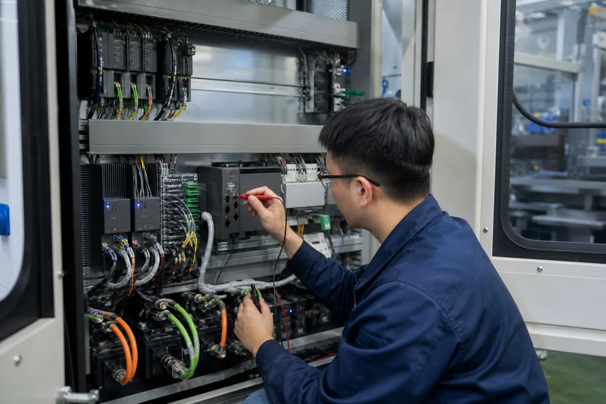
Axis control module: the single- or double-axis motor module that drives one CNC axis from a shared DC link
The per-axis power and control module in a modular CNC drive line-up · fed from a shared DC link, rated by rated, base-load, S6 and peak current, and supplied as single- or double-axis units
In a modular drive system for a CNC machine, the servo axes do not each get a separate amplifier with its own mains connection. They share one supply (a line module or power supply module) that turns the mains into a DC link, and each axis gets a narrow module that converts that DC link back into motor current. These axis modules are what this page covers: how they connect to each other, how their current ratings are stated, when a double-axis module beats two single ones, and what control and safety functions sit inside them.
Axis (motor) modules of modular multi-axis drive systems for CNC machine tools and similar machines: single- and double-axis modules on a shared DC link, their supply, DC link and 24 V busbars, current ratings, and the control and safety functions built into them. Stand-alone servo amplifiers with their own mains input are covered on the Servo drive page; matched motor-and-drive packages with cables on the Servo motor and drive set page; motion controllers that command the axes on the Motion controller page; PC plug-in motion cards on the PCI and PCIe motion control card page; the NC kernel and operator panel on the CNC controller page.
CNFX editorial research · Sources checked October 12, 2026 · 3 sources
Supply module, DC link busbars and axis modules side by side
Siemens' NC 61 catalogue (2007/2008, for SINUMERIK machine tool systems) describes SINAMICS S120 booksize Motor Modules as single-axis modules with rated output currents of 3 A to 200 A and two-axis Double Motor Modules of 3 A to 18 A, all of which can be operated on Smart Line Modules or Active Line Modules of the matching voltage range. They run on a DC link of 510 to 720 V DC, corresponding to a line voltage of 380 to 480 V three-phase. [1]
Beckhoff builds the same arrangement in its AX8000 multi-axis servo system: the required number of 1- or 2-channel axis modules is connected to a central power supply module or to a combined supply and axis module. [3] Its catalogue lists supply modules of 20 A DC (AX8620) and 40 A DC (AX8640), a DC supply module of 50 A DC for 24 to 680 V DC (AX8600), single-axis modules of 8, 18 and 28 A, a dual-axis module of 2 × 6 A, combined supply-and-axis modules of 25 and 40 A, and option modules for extra capacitance, regeneration and coupling. [3]
Editorial note: the supply module, not the axis modules, connects to the mains; specify its rating from the sum of the axes' DC link currents at the duty they actually run together, and decide early whether braking energy is to be returned to the line or burned in a resistor, since that changes the supply module type.
Connection on each Siemens booksize Motor Module
Published value
DC link
2 connections via integrated DC link busbars, busbar capacity 100 A [1]
Electronics supply
Integrated 24 V DC busbars, capacity 20 A; extra 24 V terminal adapter above that (max. 6 mm², fused max. 20 A) [1]
Control and feedback
3 DRIVE-CLiQ sockets; communicates with a CU320 Control Unit or SINUMERIK solution line [1]
Safety
1 safe standstill input (enable pulses), 1 safe motor brake control [1]
Give the drive supplier a list of axes with motor type, continuous and peak torque or current, duty cycle and which axes accelerate together; ask for the supply module rating, DC link layout and braking concept that result.
02
Four current ratings on one module: rated, base-load, S6 (40%) and maximum
An axis module's datasheet does not give one current but four, each for a different duty. Siemens' table for its 3–30 A booksize Single Motor Modules shows them side by side. [1]
The ratings apply at a rated pulse frequency of 4 kHz, an ambient of 0 to 40 °C without derating (derating up to 55 °C) and installation up to 1,000 m without derating (up to 4,000 m with derating). [1] Siemens also states that the DC link current figure is for dimensioning an external DC connection, and that the Line Module is dimensioned by a separate calculation in its system description. [1]
Editorial calculation: maximum current is 2.0 times rated for the 3, 5, 9 and 18 A modules (6/3, 10/5, 18/9, 36/18) but about 1.87 times for the 30 A module (56/30). A feed axis sized on peak acceleration current must be checked against Imax of the exact module, not against a fixed multiple of the rating.
These figures come from a 2007/2008 catalogue for the AA3 module generation; later S120 booksize generations carry different order numbers and ratings, so check the current Siemens data for the order number quoted.
Siemens Single Motor Module (booksize, 600 V DC link)
Ask for each axis module: rated, base-load, S6 and maximum current at the pulse frequency you will run, the ambient and altitude derating, power loss in the cabinet, and module width.
03
Two axes in one housing: Siemens Double Motor Modules from 2 × 3 A to 2 × 18 A
Siemens' D 21.1 catalogue (2006) lists booksize Double Motor Modules with rated output currents of 2 × 3, 2 × 5, 2 × 9 and 2 × 18 A on the same 510–720 V DC link, each with two plug-in motor connectors (max. 30 A) and brake connections integrated in them. [2]
Editorial calculation: two 9 A axes on one 2 × 9 A Double Motor Module take 50 mm of cabinet width and 0.16 kW of loss; on two 9 A Single Motor Modules they take 2 × 50 = 100 mm and 2 × 0.080 = 0.16 kW. [2][1] The double module halves the width at the same loss, but the two axes then share one housing and one replacement part. The two catalogues are different editions (2006 and 2007/2008), so confirm the comparison with current data.
Beckhoff's AX8000 range likewise pairs a dual-axis module (2 × 6 A) with single-axis modules up to 28 A, so a line-up can mix two-axis modules for small axes with single-axis modules for large ones. [3]
Inside the module: current loop at 62.5 µs and drive-integrated safety
Beckhoff states that the AX8000's hardware-implemented current controller reacts to setpoint deviations within 1 µs, that its shortest current controller cycle time is 62.5 µs at a switching frequency of 8 kHz, and that its EtherCAT process data are handled in hardware so the minimum EtherCAT cycle time is also 62.5 µs; distributed clocks synchronise the drive axes, for example on machine tools. [3]
The older Siemens booksize modules provide the basic hardware for safety in the module itself — a safe standstill input on the enable pulses and safe motor brake control. [1] Editorial note: on a CNC machine the safety functions required for setting-up with the door open (reduced speed, safe stop) depend on the machine's risk assessment; ask whether they run in the axis module, in a separate safety controller, or in the CNC, and which performance level each reaches.
Drive-integrated safety in AX8000 with TwinSAFE
Functions or rating
Standards
EN ISO 13849-1:2015 Cat. 4, PL e; EN 61508:2010 SIL 3; EN 62061 SIL CL3 [3]
Paste it into your enquiry below or into an email to a maker, then replace every bracket.
Axes: [list; motor type; continuous and peak current; duty cycle]
Simultaneity: [which axes accelerate or brake together]
Supply: [mains voltage; braking energy return or resistor]
Modules: [single or double-axis; width limits in the cabinet]
Control: [CNC or controller; bus and cycle time]
Feedback: [encoder type and interface]
Safety: [required functions and PL or SIL]
Environment: [cabinet temperature; altitude; pulse frequency]
Explore company information and manufacturing capabilities, then discuss the scope of your project with a relevant supplier.
Share this page
Compiled and source-reviewed by the CNFX editorial team.
Each manufacturer above links to the page on that company's own website where the product is listed, with the date we checked it. How we source and review
· Page last updated 13 October 2026
Buyer questions
What is an axis module in a CNC drive system?
It is the per-axis motor module that converts a shared DC link into motor current; Siemens' S120 booksize modules run on 510–720 V DC from a Line Module, and Beckhoff's AX8000 axis modules connect to a central power supply module. [1][3]
What is the difference between rated and maximum current on a motor module?
Siemens lists for its 9 A module a rated 9 A, a base-load 7.7 A, 10 A for S6 40% duty and a maximum of 18 A. [1]
What sizes do double-axis motor modules come in?
Siemens lists booksize Double Motor Modules of 2 × 3, 2 × 5, 2 × 9 and 2 × 18 A; Beckhoff's AX8000 has a 2 × 6 A dual-axis module. [2][3]
How fast is the current loop in a modern axis module?
Beckhoff gives a shortest current controller cycle of 62.5 µs at 8 kHz switching for AX8000, with reaction to setpoint deviations within 1 µs. [3]
Sources and what still needs a direct check
Sources checked 2026-10-12. Single Motor Module ratings, interfaces and environmental limits come from Siemens' NC 61 catalogue (2007/2008); Double Motor Module data from Siemens' D 21.1 catalogue (2006), both in distributor-hosted copies; the modular line-up, current-loop timing and safety functions of a current system from Beckhoff's AX8000 product pages.