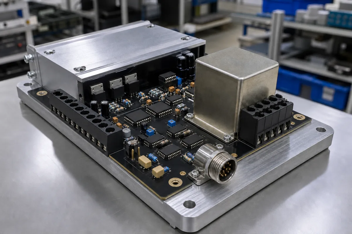
Amplifier and summing for a four-cell weighing platform
The board in the illustration is an amplifier on an aluminium base, with screw terminals for the load-cell lines, a circular sensor connector, a shielded component and trimming potentiometers. In a platform scale it sits behind a junction box that sums four load cells, and its job is measured in microvolts: each displayed scale step is a tiny change in a bridge signal that has travelled through the summing box and the cable.
Covers the amplifier and summing arrangement of multi-load-cell weighing platforms: minimum input voltage per verification scale interval and number of intervals in OIML R76 type approvals, signal budget from load-cell sensitivity and excitation, 4- and 6-wire connection and cable length limits, junction boxes with resistor networks for off-centre load compensation, and the corner-load test and trimming sequence. Excitation capacity, mV/V setting, analogue outputs and enclosures of strain-gauge conditioners are on Load-cell signal conditioner; multi-input DIN-rail conditioners are on Industrial signal conditioner; hopper and vessel weighing installation, including excitation versus signal trimming in summing boxes, is on Hopper and vessel weighing installation; load-cell capacity and OIML R60 load-cell classes are on Load cell scale; LED-strip signal amplifiers and web-tension amplifiers are outside this page.
CNFX editorial research · Sources checked October 13, 2026 · 3 sources
An OIML R76 certificate issued by NMi for SysTec's IT9 indicator shows the input figures an amplifier is type-approved against.
The minimum input voltage per verification interval is the smallest signal change the approved amplifier may be asked to resolve as one scale step. The platform design has to deliver more than that.
Worked budget (Editorial calculation, assumed values): four 500 kg load cells at 2 mV/V on 5 V excitation give 10 mV each at full load; summed in parallel, a 600 kg platform load produces about 600/2,000 × 10 = 3 mV. Divided into 3,000 intervals of 0.2 kg, that is 1.0 µV per interval, five times the 0.2 µV minimum. With zener barriers the excitation drops to 2.44 V, the signal to about 1.46 mV and 0.49 µV per interval, still above the barrier configuration's 0.33 µV.
Max. scale intervals, analog cells, no overvoltage protection
10,000
Same, with overvoltage protection
8,750
Excitation
5 V square wave
Minimum input voltage per verification scale interval
0.2 µV
Load-cell resistance
43 to 3,300 Ω
Interface
6-wire with sense, may be configured as 4-wire
With zener barriers: max. intervals / excitation / µV per interval
6,000 / 2.44 V square wave / 0.33 µV
Fraction of MPE taken by the indicator
0.5
Max. load platforms
8
The load cells, capacity and interval are assumptions for illustration. Ask the supplier for the type-approval certificate of the actual amplifier or indicator and check µV per interval with your own load-cell data.
02
Cable length and sense lines
The same certificate limits cable length between the indicator and the junction box or load cells as metres per mm² of conductor cross-section: 2,712.4 m/mm² without overvoltage protection and 2,909.3 m/mm² with it, using sense lines; 5,782.5 m/mm² in the zener-barrier configuration. Where sense lines are not used (4-wire), the load cells must be connected directly, without junction box or extension cable.
Sense lines let the amplifier measure the excitation actually arriving at the cells, so the voltage drop along a long cable does not show up as a weight error; without them the cable becomes part of the calibration.
Conductor
Max. length at 2,712.4 m/mm²
0.25 mm²
≈678 m
0.5 mm²
≈1,356 m
0.75 mm²
≈2,034 m
Editorial calculation from the certificate's figure; the sense-line explanation is an editorial reading. Ask for the cable limit in the approval of the instrument you buy, and whether a 4-wire connection is allowed with a junction box.
03
Corner load: mechanics first, then trimming
ICS Schneider's guide to corner load on platform scales starts with a scale that reads 200.0 kg with a test weight in the centre and 199.6, 200.2, 199.9 and 200.1 kg with the same weight in the four corners.
The corner spread there is 0.6 kg, 0.3% of the load (Editorial calculation). The guide lists mechanical causes (uneven mounting surface, distorted frame, side forces, force shunts, incorrect force introduction, a cell not fully loaded) and electrical ones (different cell sensitivities, mV/V tolerances, cable resistances, faulty terminals, drifting cells). Corner adjustment must not hide mechanical faults: check platform, supports, cell mounting and force path first; only then balance remaining signal differences in the summing or junction box; and check the centre load again afterwards.
HBM's VKK1-4A and VKK1R-4 junction boxes connect up to four load cells in parallel and include a resistor network for off-centre load compensation: 0.39, 0.82, 1.50 and 3.00 Ω per cell, giving 0.39 to 5.71 Ω in 15 steps. The procedure is to load the corners, read the correction from the diagram in the mounting instructions and switch in the resistor. The boxes are IP65, in coated die-cast aluminium or 1.4301 stainless steel.
Step (ICS Schneider; HBM)
Action
1
Check mechanics: supports, mounting, force shunts, cables touching the platform
2
Place the test weight in the centre, then each corner; record readings
3
Trim the junction box (HBM: switch in resistor steps per the diagram)
4
Re-check the centre reading
5
Document the corner test
The HBM step sum (0.39 + 0.82 + 1.50 + 3.00 = 5.71 Ω) is an Editorial check. Ask whether the junction box trims by resistors or potentiometers, and for a corner test record after installation.
04
What to give a supplier for a platform amplifier
Paste it into your enquiry below or into an email to a maker, then replace every bracket.
State platform capacity and scale interval, number of load cells with their capacity, sensitivity (mV/V) and resistance, legal-for-trade class and number of intervals, cable length and conductor size, whether zener barriers or overvoltage protection are needed, and the junction box type. Ask for the type-approval certificate with µV per interval, maximum intervals, excitation and cable-length figures, 4- or 6-wire connection, and the corner-load trimming method.
1 company lists this product among what they make. Company figures are quoted from each
company's own website; every card states where the relationship came from.
Shenzhen Huachuang Testing Technology Co., Ltd.
TBC
Huatran's site lists analog and digital signal amplifiers alongside its multi-axis force sensors, force sensors and torque transducers; ask for input sensitivity, excitation and approval status for weighing use.
Explore company information and manufacturing capabilities, then discuss the scope of your project with a relevant supplier.
Share this page
Compiled and source-reviewed by the CNFX editorial team.
Each manufacturer above links to the page on that company's own website where the product is listed, with the date we checked it. How we source and review
· Page last updated 13 October 2026
Buyer questions
What does 'minimum input voltage per verification scale interval' mean?
The smallest signal step the approved amplifier may resolve as one interval; NMi's certificate for SysTec's IT9 gives 0.2 µV at 5 V excitation for up to 10,000 intervals. [1]
How long can the load-cell cable be?
The same certificate allows 2,712.4 m per mm² of conductor with sense lines (no overvoltage protection); without sense lines the cells must connect directly, without junction box or extension. [1]
How is off-centre load corrected?
After checking the mechanics, by trimming the cell signals in the junction box; HBM's VKK1-4A uses a switchable resistor network of 0.39 to 5.71 Ω in 15 steps. [2][3]
Can corner trimming fix any corner error?
No: ICS Schneider warns that binding corners, unloaded cells or force shunts must be fixed mechanically first, and the centre load re-checked after trimming. [3]
Sources and what still needs a direct check
Sources checked 2026-10-13. An OIML type-approval certificate, a junction-box datasheet from a load-cell maker and a weighing distributor's corner-load guide.