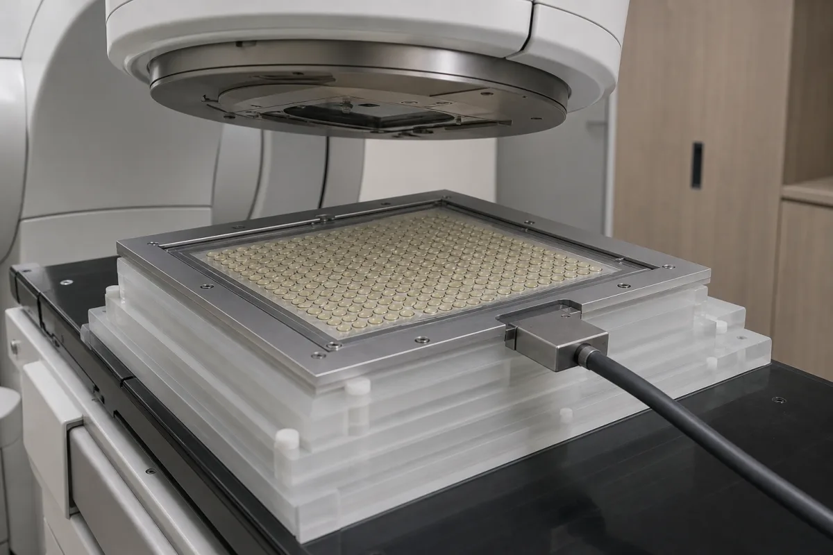
2D ionization chamber arrays for radiotherapy machine and patient-specific QA · number of chambers and spacing, active area, chamber volume and electrode gap, photon (IMRT/VMAT) vs proton and carbon beams, dose-rate linearity and ion recombination, wireless and battery operation
An ionization chamber array is a flat panel of hundreds to over a thousand small air-filled ionization chambers that measures a radiotherapy beam's two-dimensional dose distribution in one exposure. Medical physicists use it on the treatment couch, on its own or inside a phantom, to check machine output and profiles and to verify patient treatment plans before delivery. Ask three things first: the beam type — photon IMRT/VMAT, proton or heavy ion — and dose rates it must handle; the resolution and active area needed for your fields; and how it connects, is powered and is analysed in software.
Two-dimensional ionization chamber arrays for radiotherapy quality assurance — photon and particle-therapy arrays, with phantoms, gantry sensors and analysis software. Single reference ionization chambers, diode and diamond detector arrays, film, electronic portal imaging and water-tank scanning systems are outside this page except where compared.
CNFX editorial research · Sources checked October 12, 2026 · 4 sources
IBA Dosimetry's MatriXX Resolution, a detector array for IMRT and VMAT patient QA and machine QA, has 1,521 ionization chambers at 6.5 mm resolution over a 25.3 × 25.3 cm² field, with combined-field measurement for fields larger than 40 cm. It places 39 chambers on each centreline for penumbra detail and 9 chambers at the centre for dose and calibration measurements, offers 50% more measurement points than earlier MatriXX detectors, runs on battery with wireless or Ethernet connection, triggers on the beam, supports flattening-filter and flattening-filter-free beams, and is aligned on the couch by laser; IBA states a workflow of under 5 minutes (typ.) from setup to result. [1]
Editorial calculation: 39 chambers across 25.3 cm at 6.5 mm pitch gives 39 × 39 = 1,521 chambers, matching the stated count; doubling the pitch to 13 mm over the same area would leave about 20 × 20 = 400 chambers, roughly a quarter of the measurement points. [1]
Give the supplier the beam types and energies (photon FF/FFF, electron, proton, carbon), treatment techniques (IMRT, VMAT, PBS), dose and dose-rate range, required resolution and field size, phantom and gantry-angle needs, connection (wireless, Ethernet) and power, analysis software and integration with your treatment planning and record-and-verify systems, calibration and service, and quantity.
02
Match chamber design to beam type and dose rate
IBA's MatriXX AiR, a wireless array for patient-specific QA in proton and heavy-ion therapy, has 1,521 air-vented parallel-plate chambers at 6.5 mm centre-to-centre spacing over 25 × 25 cm, a single chamber volume of 8 mm³ and a 1 mm electrode gap, is designed to support ultra-high dose rate (UHDR) and FLASH protocols with minimal recombination loss, applies automatic temperature and pressure correction, runs on battery or mains, and weighs about 7.3 kg. [2] A 2015 study in the Journal of Applied Clinical Medical Physics on pencil-beam scanning proton QA explains that ion recombination changes with beam current, duration and dose rate; it measured up to 4% dose nonlinearity with an earlier general array but under 1% with a proton-specific array using 1,020 vented parallel-plate chambers at 7.6 mm spacing. [3]
Editorial note: ask suppliers for recombination or dose-linearity data at your machine's instantaneous dose rate, especially for pencil-beam scanning or FLASH work, rather than relying on photon-beam specifications.
03
Compare a second array's chamber size, spacing and dose-rate range
PTW's OCTAVIUS Detector 1500 is a photon-beam array of 1,405 plane-parallel vented ionization chambers, each 4.4 × 4.4 × 3 mm (0.06 cm³), at 7.1 mm centre-to-centre spacing over a maximum field of 27 × 27 cm². PTW lists reproducibility of ≤±0.5%, zero dead time, a 100 ms repetition rate, dose and dose-rate resolution of 0.1 mGy and 0.1 mGy/min, a measurement range of 0.25 to 800 Gy/min, and a reference point 7.5 mm below the array surface. The array measures 467 × 300 × 22 mm, weighs 6 kg, runs on 100–240 V AC and connects by Ethernet. Two measurements can be composed to extend the verification length to 48 cm, and the array is used with PTW's OCTAVIUS 4D rotating phantom for IMRT, VMAT and SRS/SBRT plans, including FFF beams. [4]
Editorial calculation: a 0.06 cm³ chamber is 60 mm³, 7.5 times the 8 mm³ chamber IBA states for its MatriXX AiR, and the 7.1 mm spacing is 0.6 mm coarser than IBA's 6.5 mm. The upper limit of 800 Gy/min is about 13.3 Gy/s, so an array intended for ultra-high dose rate work needs separate linearity data at that machine's pulse dose rate. [4][2]
Questions for an array supplier: chambers, linearity, software, approvals
When requesting quotations, ask each supplier for chamber count, spacing and volume, dose-rate linearity data, compatible phantoms and gantry sensors, software features and regulatory status in your country.
05
Chamber matrix, electronics, corrections and software
Chamber volume and electrode gap are the rows tied to recombination at high dose rate, discussed above. [2][3]
Channels, pitch, dose-rate range and linearity for the array
The dose-rate and uncertainty rows carry the recombination question; their published figures come from different arrays and beams, so ask for data at your machine's dose rate.
Explore company information and manufacturing capabilities, then discuss the scope of your project with a relevant supplier.
Share this page
Compiled and source-reviewed by the CNFX editorial team.
Each manufacturer above links to the page on that company's own website where the product is listed, with the date we checked it. How we source and review
· Page last updated 13 October 2026
Buyer questions
How many chambers does a 2D array have?
IBA's MatriXX Resolution has 1,521 chambers at 6.5 mm spacing over 25.3 × 25.3 cm². [1]
Why does dose rate matter for proton QA arrays?
Ion recombination changes with beam current, duration and dose rate; one study found up to 4% nonlinearity with a general array versus under 1% with a proton-specific one. [3]
Can arrays work wirelessly?
Yes; IBA's MatriXX Resolution and AiR are battery-powered with wireless connection. [1][2]
How large are the chambers in a 2D ionization chamber array?
One maker lists 1,405 vented chambers of 4.4 × 4.4 × 3 mm (0.06 cm³) at 7.1 mm spacing over 27 × 27 cm²; another lists 8 mm³ chambers at 6.5 mm. [4][2]
Sources and what still needs a direct check
Sources checked 2026-10-12. IBA Dosimetry describes its own arrays; the JACMP article is a peer-reviewed clinical physics study.