Editorial Technical Reference

LED Array Module

This page explains how LED Array Module is classified within Computer, Electronic and Optical Product Manufacturing. Technical values and manufacturer relationships are research references; confirm the current specification and supplier evidence for each order.

Technical Definition & Core Assembly

A modular assembly of multiple LED chips arranged in a specific pattern, designed as a replaceable component within a programmable lighting system.
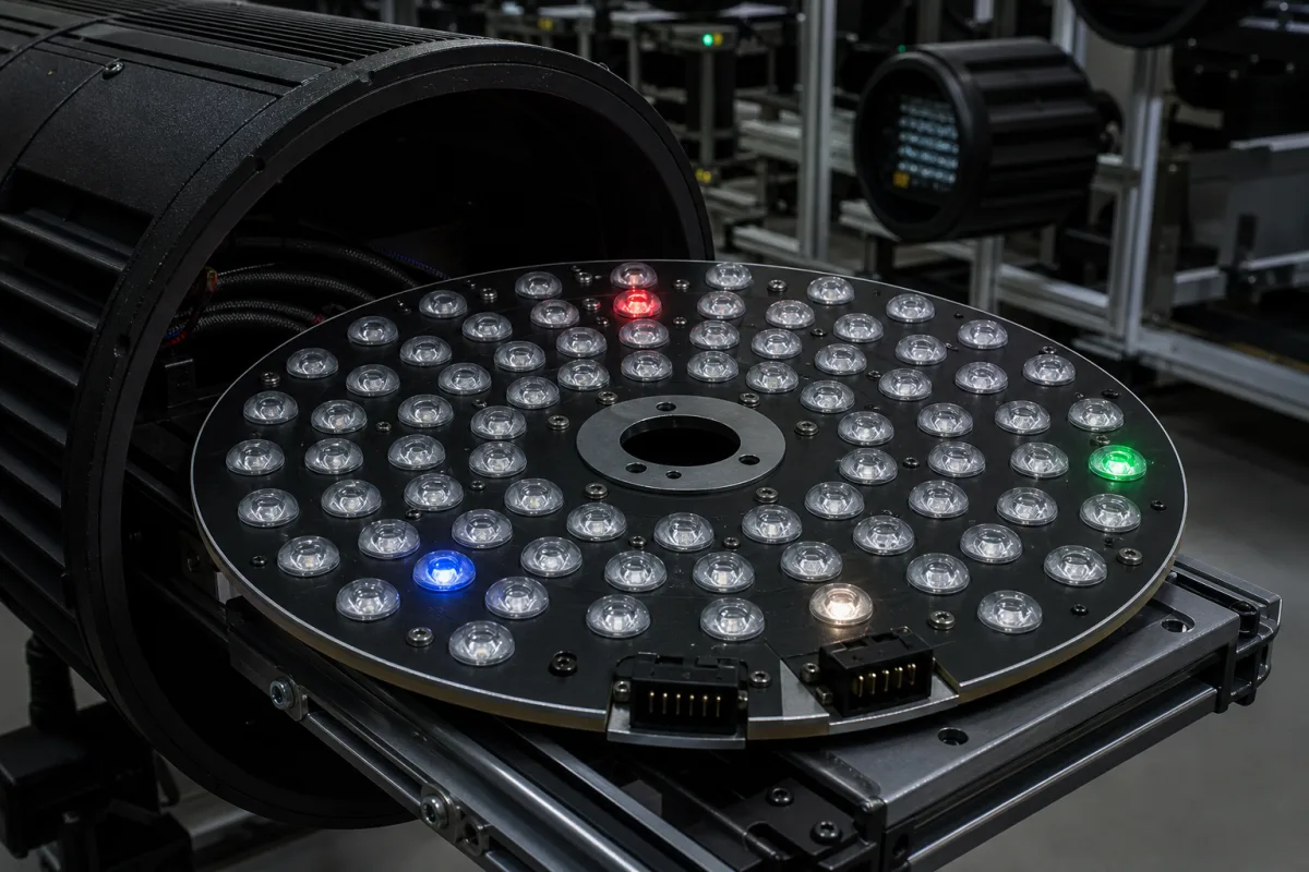
Representative product image. Confirm appearance and specifications with the manufacturer.

Product Specifications

Technical details and manufacturing context for LED Array Module

Definition
The LED Array Module is a critical component of the Programmable Lighting System, consisting of multiple individual LED chips mounted on a substrate and arranged in a predetermined configuration (such as matrix, linear, or circular patterns). It serves as the primary light-emitting element that can be individually controlled or addressed by the system's controller to create dynamic lighting effects, color mixing, and intensity variations. Within the system, it interfaces with power supplies, drivers, and control circuits to execute programmed lighting sequences. The module is designed as a replaceable part, allowing for maintenance or upgrades without replacing the entire lighting system. Its construction includes a PCB substrate that provides electrical connections and mechanical support, with LED chips mounted and encapsulated using epoxy or silicone for protection. Thermal interface materials are used to manage heat dissipation, ensuring reliable operation within specified temperature ranges. The module's performance is characterized by parameters such as the number of LED chips (24–96), power consumption (30–120 W), forward voltage (24–48 V DC), luminous flux (3000–12000 lm), color temperature (2700–6500 K), color rendering index (80–95 Ra), operating temperature (-20 to 60 °C), storage temperature (-40 to 85 °C), IP rating (IP54–IP65 per IEC 60529), module dimensions (100×100 to 300×300 mm), weight (0.5–2.5 kg), and lifetime (50000–100000 hours per IES LM-80). These values are typical ranges and must be verified for the specific model and application. The module is intended for use in programmable lighting systems where dynamic control is required. It is not a standalone luminaire and requires appropriate drivers and controllers. For procurement, verify model-specific specifications and compliance with relevant standards with the legal manufacturer or supplier.
Working Principle
The module operates by converting electrical energy into light through semiconductor electroluminescence. When forward voltage is applied to the LED chips, electrons recombine with electron holes within the device, releasing energy in the form of photons. The array configuration allows for individual or grouped control of LEDs, enabling complex lighting patterns, color temperature adjustments, and dimming capabilities when integrated with the system's programmable controller. The controller sends signals to drivers that regulate current to each chip or group, thereby controlling intensity and color. Heat generated during operation is conducted through the substrate and thermal interface material to a heat sink or housing, maintaining junction temperature within safe limits. The module's design ensures that each chip can be addressed independently, providing flexibility in creating dynamic lighting effects.
Common Materials
LED chips (semiconductor material), PCB substrate, Encapsulation epoxy/silicone, Thermal interface material
Technical Parameters
ParameterTypical rangeNotes & selection driver
Number of LED Chips24–96 pcsDetermines light output and resolution
Power Consumption30–120 WTotal module power at rated current
Forward Voltage24–48 V DCTypical operating voltage range
Luminous Flux3000–12000 lmTotal luminous output at rated current
Color Temperature2700–6500 KCCT range available
Color Rendering Index80–95 RaHigher CRI for accurate color
Operating Temperature-20–60 °CAmbient temperature range
Storage Temperature-40–85 °CNon-operating storage range
IP RatingIP54–IP65Dust and water resistanceIEC 60529
Module Dimensions100×100–300×300 mmLength × width, varies by chip count
Weight0.5–2.5 kgDepends on heat sink and housing
Lifetime50000–100000 hL70 lumen maintenanceIES LM-80

Ranges are indicative industry figures for RFQ preparation, not a supplier commitment. Confirm every value and standard with the legal manufacturer before ordering.

Components / BOM
  • LED chips Part
    Primary light-emitting semiconductor elements
    Material: Gallium arsenide/Gallium nitride semiconductor
  • PCB substrate Part
    Provides electrical connections and mechanical support for LED chips
    Material: FR-4 or aluminum PCB
  • Thermal pad Part
    Dissipates heat from LED chips to prevent overheating
    Material: Thermal conductive material
  • Connector Part
    Electrical interface for power and control signals
    Material: Plastic with metal contacts

Applied To / Applications

This component is essential for the following industrial systems and equipment:

Industrial Ecosystem & Supply Chain Structure

Complementary Systems
Downstream Applications
Specialized Tooling

Application Fit & Sizing Matrix

Operational Limits
pressure: Atmospheric only (non-pressurized enclosure)
other spec: Max forward current: 350mA per LED, IP65 ingress protection rating
temperature: -40°C to +85°C operating, -55°C to +100°C storage
Media Compatibility
✓ Indoor ambient air ✓ Dry industrial environments ✓ Sealed optical assemblies
Unsuitable: Direct water immersion or high-humidity condensing environments
Sizing Data Required
  • Required luminous flux (lumens)
  • Beam angle and optical distribution pattern
  • Available mounting space and thermal dissipation capacity

Reliability & Engineering Risk Analysis

Failure Mode & Root Cause
Thermal degradation
Cause: Inadequate heat dissipation leading to LED junction temperature exceeding design limits, causing phosphor degradation, color shift, and reduced luminous output.
Driver circuit failure
Cause: Electrolytic capacitor aging due to high operating temperatures, voltage spikes, or poor quality components, resulting in flickering, dimming, or complete module failure.
Maintenance Indicators
  • Visible flickering or intermittent operation indicating driver instability
  • Significant color shift or dimming compared to adjacent modules suggesting thermal stress or component degradation
Engineering Tips
  • Ensure proper thermal management by maintaining clean heat sinks, verifying adequate airflow, and avoiding operation above rated ambient temperatures
  • Implement surge protection and stable power supply with appropriate voltage regulation to prevent electrical stress on driver components

Indicative industry ranges for design and RFQ preparation. Confirm the exact figures and applicable standard with the manufacturer before specifying.

Compliance & Manufacturing Standards

Applicable Standards
ANSI/IES RP-16-17 - Nomenclature and Definitions for Illuminating Engineering CE EN 62471:2008 - Photobiological Safety of Lamps and Lamp Systems

Quoted from the published standard.

Manufacturing Precision
  • LED Placement: +/-0.1mm
  • Thermal Interface Flatness: 0.05mm
Quality Inspection
  • Luminous Flux and Chromaticity Test
  • Thermal Cycling and Humidity Test

Manufacturers of LED Array Module

Manufacturer profiles associated with LED Array Module.

Sourcing LED Array Module from China?
Tell us your specification and target quantity — we will match it against manufacturer records and come back with the factories that fit.
Request manufacturers We manufacture this

Manufacturer listings support early research and capability understanding. They are not certification, ranking, or transaction guarantees.

Technical documentation
Request current drawings, revision history, and a signed specification sheet.
Manufacturing capability
Verify equipment lists, process limits, capacity, and representative production evidence.
Inspection readiness
Confirm test methods, calibrated equipment, sampling plans, and traceable reports.
Supplier transparency
Check the legal entity, factory address, ownership, certifications, and direct contacts.

CNFX does not score or rank suppliers. Buyers must verify all claims and documents with the legal manufacturer before ordering.

Supply Chain Compatible Machinery & Devices

Industrial IoT Gateway

The Industrial IoT Gateway is a ruggedized edge computing device designed for industrial environments.

Explore Specs →
Modular Industrial Edge Computing Device

This modular industrial edge computing device is a ruggedized system designed for deployment in harsh industrial environments to perform real-time data processing, analytics, and control functions at the network edge.

Explore Specs →
Industrial Smart Camera Module

The Industrial Smart Camera Module is a compact, self-contained vision processing unit designed for integration into industrial machinery and production lines.

Explore Specs →
Surface Mount Resistor

Passive electronic component for current limiting and voltage division in circuits

Explore Specs →

Frequently Asked Questions

What is the typical power consumption of an LED array module?

The typical power consumption ranges from 30 to 120 watts at rated current, depending on the number of LED chips and their drive conditions. Always verify the exact value for the specific module model.

Can the LED array module be used outdoors?

The module has an IP rating of IP54 to IP65 per IEC 60529, indicating dust and water resistance. However, suitability for outdoor use depends on the complete housing and installation. Confirm with the manufacturer for the intended environment.

How is the color temperature controlled?

The module supports a color temperature range of 2700 to 6500 K. Control is achieved through the programmable controller, which adjusts the current to different LED chips or groups to mix colors and achieve the desired CCT.

What is the expected lifetime of the module?

The lifetime is rated at 50,000 to 100,000 hours for L70 lumen maintenance per IES LM-80. Actual lifespan depends on operating conditions, thermal management, and driver quality. Verify with the manufacturer for specific models.

Data Basis

Editorial classification, named public sources where available, and source-reviewed manufacturer records.

Preliminary Technical Classification
This page supports structured research, RFQ preparation, and supplier evaluation. It does not replace buyer-led supplier qualification, standards review, or technical approval.
Buyer enquiry

Request manufacturing insight for LED Array Module

Ask for use case, specification boundaries, supplier type, and RFQ preparation information for this product.

Where it goes
Straight to the CNFX editorial desk, and to the manufacturer if this product is linked to a claimed profile. Nothing is broadcast to a supplier list.
Your details stay here
We do not sell or rent enquiry data, and we do not add you to a mailing list. Used only to answer this request.
No commission, no middleman
CNFX is a directory. We take no cut of any order and never negotiate on a supplier's behalf.
What we don't claim
A listing is not an endorsement. Qualify every supplier and verify every figure yourself before ordering.

Your business information is used only to process this request.

Thank you! Your message has been sent. We'll respond within 1–3 business days.
Sorry, we couldn't send your message. Please try again, or email us at contact@cnfx.com.

Need to Manufacture LED Array Module?

Compare manufacturer profiles with relevant product and process capability.

Previous Product
XY Positioning Stage
Last Product
Get QuotesChat