Lens chuck and block assembly for prescription spectacle lenses: block pieces, alloy, wax or UV-cured bonding, and the chuck that grips the block
How a spectacle lens is held for surfacing, polishing and edging · the block piece bonded to the lens, the material that bonds it, and the chuck that grips the block in each machine
A spectacle lens blank has to stay in exactly the same position through generating, fine grinding and polishing, and in Satisloh's description also coating and edging, on different machines. The method the patents describe is to bond the finished front face to a block piece and let each machine's chuck grip that block rather than the lens. The assembly therefore has three parts that are specified together: the block piece and its clamping geometry, the bonding material between block and lens, and the chuck in the machine that receives the block.
Work-holding for prescription ophthalmic lens processing: lens blocks and block pieces (metal, plastic, UV-transparent), the bonding media between lens and block (low-melting alloy, wax, UV/VIS-cured adhesives with fillers), blocking and deblocking, and the chucks that receive the block in generators, polishers and edgers. Polishing machines for precision optical lenses are covered on the Precision optical lens polishing machine page; the polishing spindles and their hydraulic, bladder and vacuum chucks on the Polishing spindle assembly for optics page; bell-clamp centring on the Precision optical lens centering machine page; and disk-substrate polishers on the Hard drive platter polishing machine page.
CNFX editorial research · Sources checked October 13, 2026 · 3 sources
Alloy, wax or UV adhesive between lens and block: 45–65 °C melts, about 3 % UV shrinkage and a 20–40 °C exotherm
The bonding layer decides how much heat the lens sees, how much it can be distorted, and how the block comes off afterwards. Two patent holders describe the options:
Satisloh lists the drawbacks of alloy and wax that UV-cured materials address: the long time before a blocked lens can be released, distortion from the heat of the molten material, and possible contamination of the lens. [1] Europtica adds that modern plastic lenses are heat sensitive, which limits bonding materials to those that need no high application temperature. [3]
Editorial calculation: 3 % shrinkage of a 3 mm adhesive layer is about 0.09 mm, while the same 3 % on a 6 mm section under a bifocal segment (assuming a 6 mm layer for illustration; the patent gives no thickness for that section) is about 0.18 mm; that difference across the lens is the distortion Satisloh's filled adhesive is meant to reduce. [1]
Bonding medium
What the patents state
Low-melting alloy
Europtica writes that the “most commonly used technique” in blocking is a low-melting alloy flowed between button and lens, removed afterwards in a hot water reclaim tank, and notes that such alloys contain materials such as lead and cadmium [3]
Alloy or wax in a capsule
Europtica's capsule button holds a material that melts at 45 to 65 °C behind a flexible membrane (1 mm thick in its example); wax cools more slowly than alloy, and chilled water can speed solidification [3]
UV-cured adhesive
Satisloh cites prior UV blocking material with shrinkage of about 3 %, acceptable in layers under about 3 mm; depending on chemistry, shrinkage of 2 to 10 % or more [1]
Heat during UV cure
The exothermic reaction can raise the material 20 to 40 °C above its starting temperature, causing thermal stress from the different expansion of lens, block and adhesive [1]
UV adhesive with filler
Filler particles of 1 mm or less, smaller than the minimum gap of 2 mm preferred, reduce shrinkage at least by their volume fraction and reduce the exotherm [1]
State the lens materials (CR-39, polycarbonate, high index, mineral glass), the maximum temperature the coated front face may see, whether alloy is acceptable on site, and the deblocking method available.
02
The block piece and how the chuck grips it: three clamping lugs, forces that cancel at each lug, and a UV-transparent body under 1 % water absorption
Satisloh's block-piece patent describes a plastic block designed around the chuck that will hold it:
Satisloh's adhesive patent gives the conventional reference point: the lens is joined to a lens block, for example one according to the German standard DIN 58766, and the block is then gripped by a chuck or other coupling during generating. [1] The block-piece patent explains why the clamping forces are kept at the lugs: the body can be made from a softer plastic without the chuck's force reaching and deforming the lens. [2]
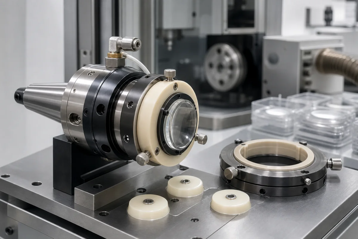
The image above shows a chuck of this kind with a taper shank and an air connection, a plastic holder ring around a lens at its face, and spare plastic pads and a ring on the table beside it.
Feature
Description in the patent
Body
Injection-moulded in one piece from plastic; transmits UV and visible light so the blocking adhesive can be cured through it [2]
Water absorption
Less than 1 % by weight at saturation, measured to DIN EN ISO 62 [2]
Clamping portion
Three radially extending clamping protrusions, distributed non-uniformly so they also fix the rotational position in the chuck [2]
Clamping forces
Applied in the circumferential direction to the two side faces of each protrusion, so they cancel at the protrusion rather than passing through the whole body [2]
Centering
Inclined outer faces and axial end portions of the protrusions locate the block in the chuck of each machine [2]
Name the machines the block must fit (generator, polisher, edger, coater), their chuck type and the block standard in use, and ask for the block material's water absorption and UV transmission if UV blocking is planned.
03
Block curves and deblocking: one curve instead of seven costs 10–15 % more blocking material, and a 50 °C bath softens the bond
Two practical choices follow from the bonding material: how many block curves the lab stocks, and how the lens is released.
Editorial calculation: the aluminium fibres cut the microwave time for a 25 °C rise from 20 s to 15 s, a quarter less (5 ÷ 20). [1] Stocking one or two block curves instead of seven trades 6 to 15 % more blocking material for fewer block types to manage, which Satisloh argues is compensated by the simpler block inventory. [1]
Item
Value from Satisloh's adhesive patent
Material increase with one block curve
10 to 15 % more blocking material than with 7 block curves; 6 % more with two curves [1]
Filled adhesive at 40.4 Shore D; 28 Shore D at 50 °C; filler Tg 36 °C; minimum gaps under 0.5 mm possible [1]
Filler Tg range claimed
25 to 80 °C; 80 °C is given as the temperature that could permanently damage a surfaced lens [1]
Faster heating for deblocking
1 to 2 % aluminium fibres: 15 s of microwave exposure raised the material 25 °C from 30 °C, against 20 s without fibres [1]
Give the range of front base curves processed, the number of block curves you are willing to stock, and the deblocking equipment (hot water, microwave, mechanical).
04
Block and chuck details to send
Paste it into your enquiry below or into an email to a maker, then replace every bracket.
Lenses: [materials; diameter range; base curve range]
Bonding: [alloy; wax; UV adhesive; filler]
Block: [standard; metal or plastic; number of curves]
Machines: [generator; polisher; edger; coater; chuck type]
Deblocking: [hot water; microwave; mechanical]
Limits: [max temperature on lens; distortion tolerance]
Explore company information and manufacturing capabilities, then discuss the scope of your project with a relevant supplier.
Share this page
Compiled and source-reviewed by the CNFX editorial team.
Each manufacturer above links to the page on that company's own website where the product is listed, with the date we checked it. How we source and review
· Page last updated 13 October 2026
Buyer questions
What is lens blocking?
Bonding the finished face of a spectacle lens blank to a lens block, which the machine chucks then grip through generating and polishing. The bond is made with alloy, wax or a UV-cured adhesive. [1][3]
At what temperature does lens blocking alloy or wax melt?
Europtica's patent gives a range of 45 to 65 °C for the low-melting material in its blocking capsule. [3]
Does UV blocking adhesive shrink?
Satisloh cites about 3 % shrinkage for an earlier UV blocking material and 2 to 10 % or more depending on chemistry, with the cure exotherm adding 20 to 40 °C. [1]
Sources and what still needs a direct check
Sources checked 2026-10-13. Three European patent documents from two applicants: Satisloh's EP 2 011 604 B2 on blocking with filled UV adhesive and EP 2 259 899 B2 on plastic block pieces, and Europtica International's EP 0 613 756 A1 on a capsule lens block.