Editorial Technical Reference

Camera Sensor (CMOS/CCD)

This page explains how Camera Sensor (CMOS/CCD) is classified within Computer, Electronic and Optical Product Manufacturing. Technical values and manufacturer relationships are research references; confirm the current specification and supplier evidence for each order.

Technical Definition & Core Assembly

An electronic device that converts light into electrical signals for image capture in 3D optical sensing systems.
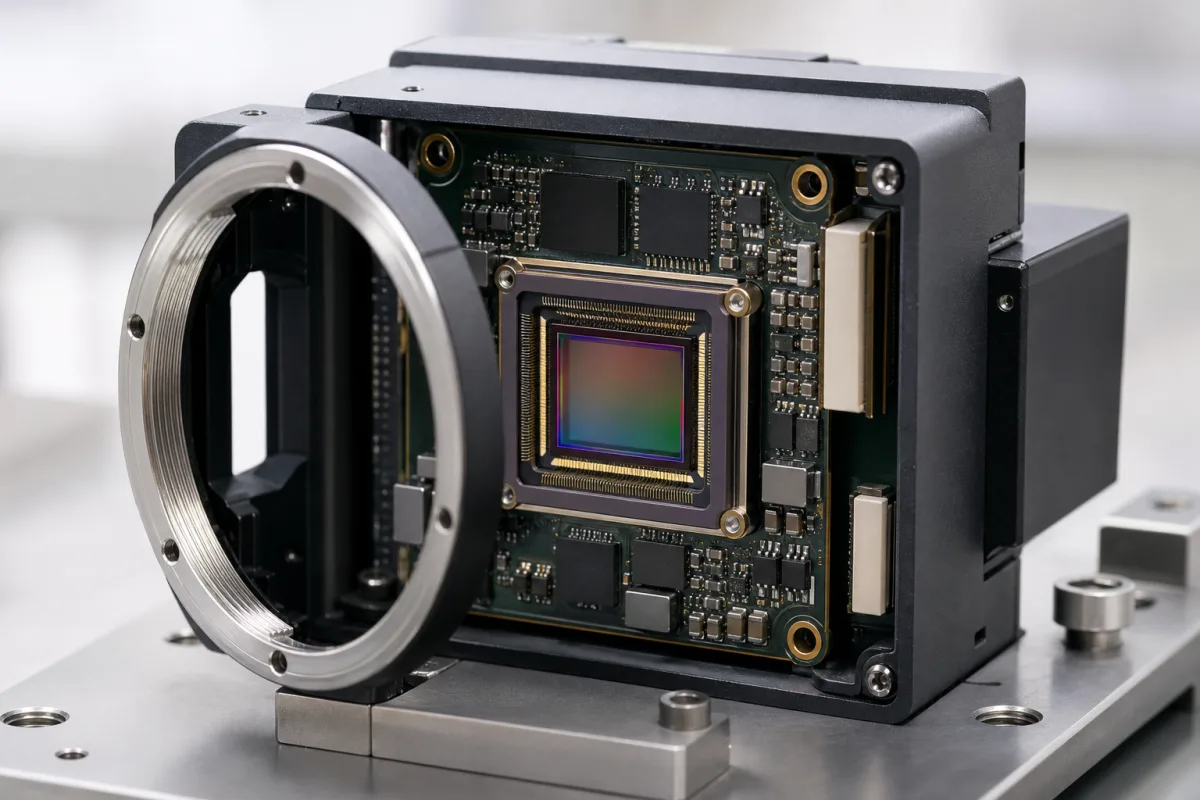
Representative product image. Confirm appearance and specifications with the manufacturer.

Product Specifications

Technical details and manufacturing context for Camera Sensor (CMOS/CCD)

Definition
A camera sensor (CMOS or CCD) is a critical component within a 3D Optical Sensor Head responsible for capturing light from the target scene. It converts incoming photons into electrical charge, which is then processed to generate digital image data. This data forms the fundamental input for subsequent 3D reconstruction algorithms, such as structured light analysis or stereo vision, enabling the measurement of depth, shape, and surface characteristics of objects. The sensor typically consists of an array of photodiodes fabricated on a silicon substrate, along with supporting circuitry for readout and amplification. A protective glass cover shields the sensitive area from environmental contaminants. Key parameters include resolution (1–50 MP), optical format (1/4–1 inch), pixel size (1.0–10 µm), frame rate (30–240 fps), dynamic range (60–100 dB), signal-to-noise ratio (40–60 dB), supply voltage (1.8–3.3 V DC), power consumption (50–500 mW), operating temperature (-30–70 °C), storage temperature (-40–85 °C), interface options (MIPI, LVDS, parallel), package types (CSP, COB, LCC), and weight (0.5–5 g). These values are typical ranges and must be verified for the specific model and application. The sensor's performance directly influences the accuracy and reliability of 3D measurements. When selecting a sensor, consider factors such as required resolution, speed, light sensitivity, and environmental conditions. Interface compatibility with the processing unit is essential. Verification of model-specific specifications and compliance with applicable standards should be confirmed with the legal manufacturer or supplier. Maintenance signals include image artifacts, dead pixels, or reduced sensitivity, which may indicate sensor degradation or contamination. Failure boundaries are defined by the sensor's operating limits; exceeding them can cause permanent damage. Proper handling and adherence to specified conditions are necessary for reliable operation.
Working Principle
Light from the scene passes through the sensor's lens and micro-lens array, striking an array of photodiodes (pixels). In a CCD (Charge-Coupled Device) sensor, accumulated charge is transferred sequentially to a readout amplifier. In a CMOS (Complementary Metal-Oxide-Semiconductor) sensor, each pixel typically has its own amplifier, allowing for faster and more flexible readout. The electrical signal is then digitized by an analog-to-digital converter (ADC) to produce a digital image.
Common Materials
Silicon (for photodiodes and circuitry), Glass (for protective cover)
Technical Parameters
ParameterTypical rangeNotes & selection driver
Resolution1–50 MPHigher resolution for finer detail
Optical Format1/4–1 inchLarger format for better light sensitivity
Pixel Size1.0–10 µmLarger pixels improve low-light performance
Frame Rate30–240 fpsHigher for fast motion capture
Dynamic Range60–100 dBWider range for high-contrast scenes
Signal-to-Noise Ratio40–60 dBHigher is better for image quality
Supply Voltage1.8–3.3 V DCTypical for CMOS/CCD sensors
Power Consumption50–500 mWLower for battery-powered devices
Operating Temperature-30–70 °CExtended range for industrial use
Storage Temperature-40–85 °CNon-operating condition
InterfaceMIPI, LVDS, parallelDigital output options
Package TypeCSP, COB, LCCAffects size and integration
Weight0.5–5 gFor compact designs

Ranges are indicative industry figures for RFQ preparation, not a supplier commitment. Confirm every value and standard with the legal manufacturer before ordering.

Components / BOM
  • Photodiode Array
    Converts incoming light photons into electrical charge at each pixel location.
    Material: Silicon
  • Color Filter Array (CFA) Part
    Filters light to specific wavelengths (Red, Green, Blue) over pixels to enable color imaging.
    Material: Dyed polymer or pigment
  • Micro-lens Array
    Focuses light onto the photodiode area of each pixel to improve light collection efficiency.
    Material: Polymer or glass
  • Readout Amplifier
    Turns the collected charge into a voltage — per-chip on CCD, per-pixel on CMOS.
  • Analog-to-Digital Converter Optional
    Digitises the pixel signal on-chip; some CCD designs put this outside the sensor.

Industry Taxonomies & Aliases

Commonly used trade names and technical identifiers for Camera Sensor (CMOS/CCD).

Applied To / Applications

This component is essential for the following industrial systems and equipment:

Industrial Ecosystem & Supply Chain Structure

Complementary Systems
Downstream Applications
Specialized Tooling

Application Fit & Sizing Matrix

Operational Limits
pressure: Atmospheric (0.1-1.0 bar), not rated for pressure differentials
other spec: Humidity: 0-95% non-condensing, Vibration: 5g max, Shock: 50g max
temperature: -40°C to +85°C (operating), -55°C to +125°C (storage)
Media Compatibility
✓ Clean air environments ✓ Optical glass/quartz windows ✓ Non-corrosive gas atmospheres
Unsuitable: Direct liquid immersion or high particulate environments without protective housing
Sizing Data Required
  • Required spatial resolution (pixels/mm)
  • Field of view dimensions (mm)
  • Frame rate requirement (fps)

Reliability & Engineering Risk Analysis

Failure Mode & Root Cause
Pixel degradation
Cause: Thermal stress from prolonged operation or environmental exposure causing dark current increase, hot pixels, or dead pixel clusters
Signal processing failure
Cause: Electrostatic discharge (ESD) damage during handling or moisture ingress compromising internal circuitry and data transmission
Maintenance Indicators
  • Persistent image artifacts (streaking, fixed pattern noise, or color distortion) not resolved by cleaning
  • Intermittent signal loss or complete black/white screen output despite proper power and connection
Engineering Tips
  • Implement controlled thermal management with heatsinks or active cooling to maintain optimal operating temperature range and minimize thermal cycling stress
  • Establish ESD-safe handling protocols and maintain clean, dry environments with proper sealing to prevent contamination and moisture ingress

Indicative industry ranges for design and RFQ preparation. Confirm the exact figures and applicable standard with the manufacturer before specifying.

Compliance & Manufacturing Standards

Applicable Standards
ISO 12233:2017 (Photography - Electronic still picture imaging - Resolution and spatial frequency responses) IEC 60747-5-5 (Semiconductor devices - Discrete devices and integrated circuits - Part 5-5: Optoelectronic devices - Photocouplers) CE marking (EU conformity for electromagnetic compatibility and low voltage directives)

Quoted from the published standard.

Manufacturing Precision
  • Pixel pitch uniformity: +/- 0.5% across sensor array
  • Quantum efficiency variation: +/- 3% at specified wavelength
Quality Inspection
  • Dark current and hot pixel analysis (thermal noise testing)
  • Modulation Transfer Function (MTF) measurement for resolution verification

Manufacturers of Camera Sensor (CMOS/CCD)

Manufacturer profiles associated with Camera Sensor (CMOS/CCD).

Sourcing Camera Sensor (CMOS/CCD) from China?
Tell us your specification and target quantity — we will match it against manufacturer records and come back with the factories that fit.
Request manufacturers We manufacture this

Manufacturer listings support early research and capability understanding. They are not certification, ranking, or transaction guarantees.

Technical documentation
Request current drawings, revision history, and a signed specification sheet.
Manufacturing capability
Verify equipment lists, process limits, capacity, and representative production evidence.
Inspection readiness
Confirm test methods, calibrated equipment, sampling plans, and traceable reports.
Supplier transparency
Check the legal entity, factory address, ownership, certifications, and direct contacts.

CNFX does not score or rank suppliers. Buyers must verify all claims and documents with the legal manufacturer before ordering.

Supply Chain Compatible Machinery & Devices

Industrial IoT Gateway

The Industrial IoT Gateway is a ruggedized edge computing device designed for industrial environments.

Explore Specs →
Modular Industrial Edge Computing Device

This modular industrial edge computing device is a ruggedized system designed for deployment in harsh industrial environments to perform real-time data processing, analytics, and control functions at the network edge.

Explore Specs →
Industrial Smart Camera Module

The Industrial Smart Camera Module is a compact, self-contained vision processing unit designed for integration into industrial machinery and production lines.

Explore Specs →
Surface Mount Resistor

Passive electronic component for current limiting and voltage division in circuits

Explore Specs →

Frequently Asked Questions

What is the difference between CMOS and CCD sensors?

CMOS sensors have per-pixel amplifiers, allowing faster and more flexible readout, while CCD sensors transfer charge sequentially to a single amplifier, often providing higher uniformity. Both are used in 3D optical sensing, and the choice depends on application requirements.

How do I select the right resolution for my 3D sensing application?

Higher resolution (up to 50 MP) provides finer detail but may require more processing power and bandwidth. Consider the required measurement accuracy and field of view. Verify the sensor's resolution and other parameters with the manufacturer.

What interface options are available for camera sensors?

Common interfaces include MIPI, LVDS, and parallel. The choice depends on the processing unit's compatibility and data rate requirements. Ensure the sensor's interface matches your system design.

What are typical operating temperature ranges?

The operating temperature range is typically -30 to 70 °C, with storage from -40 to 85 °C. Exceeding these limits can cause performance degradation or permanent damage. Always verify the specific sensor's ratings.

Data Basis

Editorial classification, named public sources where available, and source-reviewed manufacturer records.

Preliminary Technical Classification
This page supports structured research, RFQ preparation, and supplier evaluation. It does not replace buyer-led supplier qualification, standards review, or technical approval.
Buyer enquiry

Request manufacturing insight for Camera Sensor (CMOS/CCD)

Ask for use case, specification boundaries, supplier type, and RFQ preparation information for this product.

Where it goes
Straight to the CNFX editorial desk, and to the manufacturer if this product is linked to a claimed profile. Nothing is broadcast to a supplier list.
Your details stay here
We do not sell or rent enquiry data, and we do not add you to a mailing list. Used only to answer this request.
No commission, no middleman
CNFX is a directory. We take no cut of any order and never negotiate on a supplier's behalf.
What we don't claim
A listing is not an endorsement. Qualify every supplier and verify every figure yourself before ordering.

Your business information is used only to process this request.

Thank you! Your message has been sent. We'll respond within 1–3 business days.
Sorry, we couldn't send your message. Please try again, or email us at contact@cnfx.com.

Need to Manufacture Camera Sensor (CMOS/CCD)?

Compare manufacturer profiles with relevant product and process capability.

Previous Product
XY Positioning Stage
Last Product
Get QuotesChat