Editorial Technical Reference

Microcontroller / FPGA

This page explains how Microcontroller / FPGA is classified within Computer, Electronic and Optical Product Manufacturing. Technical values and manufacturer relationships are research references; confirm the current specification and supplier evidence for each order.

Technical Definition & Core Assembly

A programmable digital logic device that serves as the computational core of an I/O interface board, controlling data processing, signal routing, and peripheral management.
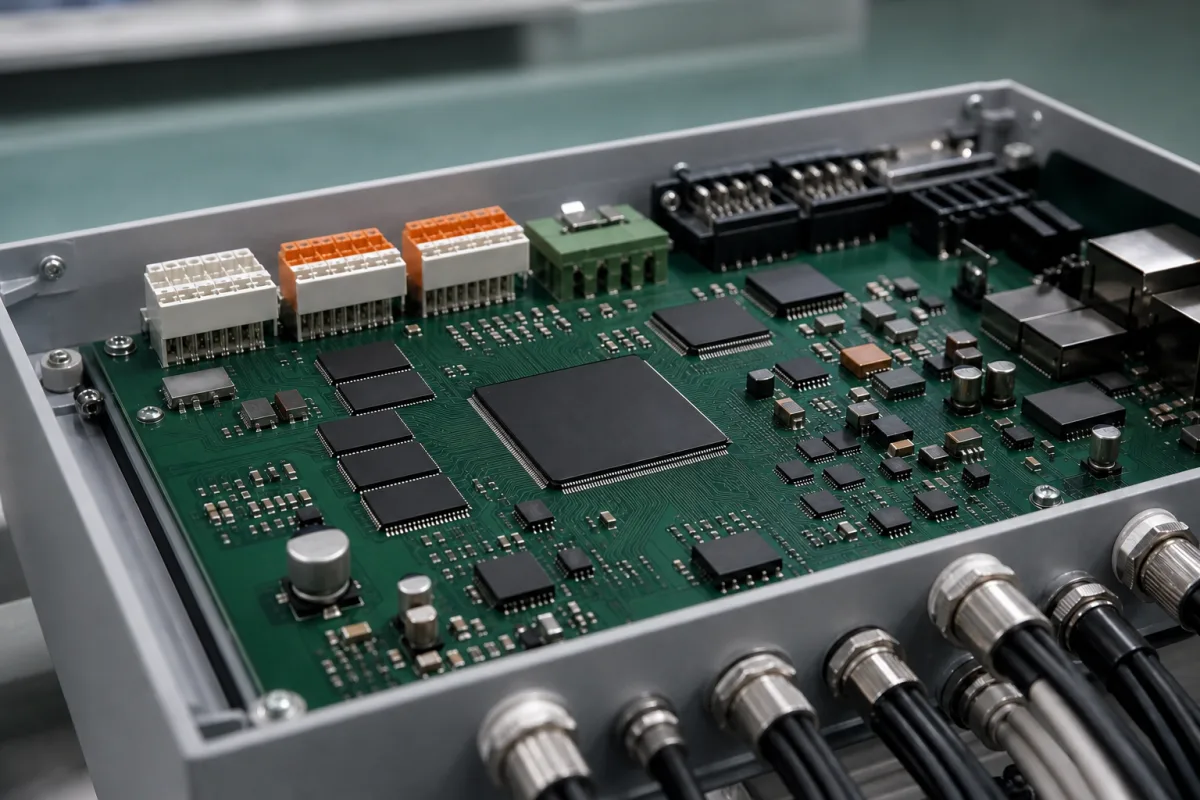
Microcontroller / FPGA in a manufacturing environment
Representative product image. Confirm appearance and specifications with the manufacturer.

Product Specifications

Technical details and manufacturing context for Microcontroller / FPGA

Definition
Within an I/O Interface Board, the microcontroller or FPGA acts as the central processing unit responsible for executing control algorithms, managing communication protocols (such as UART, SPI, I2C, Ethernet), handling analog-to-digital and digital-to-analog conversions, and coordinating timing and synchronization between various input/output channels. It provides the intelligence that transforms raw sensor data into actionable information and executes commands to actuators and other connected devices. The device is a component-level part, typically packaged in surface-mount form (QFP to BGA) and fabricated on silicon with copper interconnects and plastic/epoxy packaging. Key parameters include logic cells or equivalent gates (1K–500K), clock frequency (10–500 MHz), operating voltage (1.8–3.3 V), I/O pins (32–500), operating temperature (-40 to 85 °C), supply current (10–500 mA), program memory (16–2048 KB), RAM (2–512 KB), ADC resolution (8–16 bits), ESD protection (2–8 kV per IEC 61000-4-2), and weight (1–10 g). These values are directory reference ranges and must be confirmed for the specific model and application. The choice between a microcontroller and an FPGA depends on the required processing paradigm: microcontrollers execute sequential firmware, while FPGAs implement parallel hardware logic. For procurement, verify the exact logic capacity, speed grade, memory size, package type, and compliance with relevant standards from the legal manufacturer or supplier.
Working Principle
Microcontrollers operate as embedded computers with fixed CPU, memory, and peripherals, executing sequential instructions from stored firmware. FPGAs consist of configurable logic blocks and interconnects that can be programmed to implement parallel digital circuits, offering hardware-level speed and flexibility for specific interface tasks. Both receive power and clock signals, process input data according to programmed logic, and generate output signals to control the board's I/O operations. The device's configuration or firmware determines its behavior, and it interfaces with sensors, actuators, and communication buses. For maintenance, monitor supply current and temperature; failure may manifest as erratic I/O behavior or communication errors. Verify that the device's operating voltage and I/O levels match the board's design.
Common Materials
Silicon semiconductor, Copper interconnects, Plastic/epoxy packaging
Technical Parameters
ParameterTypical rangeNotes & selection driver
Logic Cells / Equivalent Gates1K–500K cellsDetermines design complexity and capacity.
Clock Frequency10–500 MHzHigher speeds for real-time processing.
Operating Voltage1.8–3.3 VCore and I/O voltage levels.
I/O Pins32–500 pinsNumber of configurable input/output pins.
Operating Temperature-40–85 °CIndustrial grade; extended range available.
Supply Current10–500 mADepends on logic utilization and frequency.
Program Memory16–2048 KBFlash for MCU; configuration for FPGA.
RAM2–512 KBOn-chip memory for data and variables.
ADC Resolution8–16 bitsHigher resolution for precise analog sensing.
Package TypeQFP–BGASurface mount; BGA for high pin count.
ESD Protection2–8 kVHuman body model; ensures robustness.IEC 61000-4-2
Weight1–10 gDepends on package and size.

Ranges are indicative industry figures for RFQ preparation, not a supplier commitment. Confirm every value and standard with the legal manufacturer before ordering.

Components / BOM
  • Processor Core Part
    Executes arithmetic and logic operations, controls program flow
    Material: Silicon
  • Memory Units Part
    Stores program instructions (Flash/ROM) and temporary data (RAM)
    Material: Silicon with metal layers
  • I/O Ports Part
    Physical interfaces for connecting to external sensors, actuators, and communication lines
    Material: Copper pads with gold plating
  • Clock Circuit
    Generates timing signals for synchronous operations
    Material: Quartz crystal, silicon oscillator
  • Configurable Logic Blocks Optional
    The programmable fabric on FPGA versions: logic and interconnect configured into parallel hardware.

Applied To / Applications

This component is essential for the following industrial systems and equipment:

Industrial Ecosystem & Supply Chain Structure

Complementary Systems
Downstream Applications
Specialized Tooling

Application Fit & Sizing Matrix

Operational Limits
voltage: 1.8V to 3.3V typical core/logic voltage, 5V tolerant I/O common
clock speed: 50 MHz to 500+ MHz depending on architecture and process node
temperature: -40°C to +85°C (industrial grade), -40°C to +125°C (extended/automotive grade)
power consumption: 10 mW to 5W typical active range, μW sleep modes available
Media Compatibility
✓ Industrial control systems (PLC interfaces) ✓ Automotive sensor/actuator networks ✓ Medical device data acquisition modules
Unsuitable: High-radiation environments (nuclear facilities, space applications without hardening)
Sizing Data Required
  • Required I/O pin count and types (digital, analog, high-speed)
  • Computational performance needs (MIPS, FPGA logic elements, DSP blocks)
  • Communication interface requirements (Ethernet, CAN, USB, PCIe)

Reliability & Engineering Risk Analysis

Failure Mode & Root Cause
Thermal overstress
Cause: Excessive operating temperature due to inadequate cooling, high ambient conditions, or overclocking, leading to material degradation, solder joint fatigue, and eventual functional failure.
Electrostatic discharge (ESD) damage
Cause: Accumulation and sudden discharge of static electricity during handling, installation, or operation, causing immediate or latent damage to sensitive semiconductor junctions and interconnects.
Maintenance Indicators
  • Intermittent or erratic system behavior (e.g., unexplained resets, data corruption, or logic errors) indicating potential voltage instability or thermal issues.
  • Unusual audible signs like high-pitched coil whine from nearby power supply components or audible arcing, suggesting power delivery problems or impending component failure.
Engineering Tips
  • Implement robust thermal management: Use heatsinks, thermal pads, or active cooling (fans) appropriate for the power dissipation; ensure adequate airflow in enclosures; monitor temperature with onboard sensors if available.
  • Enforce strict ESD protection protocols: Use grounded workstations, wrist straps, and antistatic packaging during handling; design PCBs with proper ESD protection circuits (e.g., TVS diodes) at interfaces.

Indicative industry ranges for design and RFQ preparation. Confirm the exact figures and applicable standard with the manufacturer before specifying.

Compliance & Manufacturing Standards

Applicable Standards
CE Marking (EU Directive 2014/35/EU Low Voltage Directive) IEC 60747-14-1 Semiconductor Devices - Integrated Circuits

Quoted from the published standard.

Manufacturing Precision
  • Package Dimension Tolerance: +/-0.1mm
  • Pin Coplanarity: 0.1mm maximum
Quality Inspection
  • Automated Optical Inspection (AOI) for solder joints and component placement
  • In-Circuit Test (ICT) for electrical connectivity and basic functionality

Manufacturers of Microcontroller / FPGA

Manufacturer profiles associated with Microcontroller / FPGA.

Sourcing Microcontroller / FPGA from China?
Tell us your specification and target quantity — we will match it against manufacturer records and come back with the factories that fit.
Request manufacturers We manufacture this

Manufacturer listings support early research and capability understanding. They are not certification, ranking, or transaction guarantees.

Share this page
Technical documentation
Request current drawings, revision history, and a signed specification sheet.
Manufacturing capability
Verify equipment lists, process limits, capacity, and representative production evidence.
Inspection readiness
Confirm test methods, calibrated equipment, sampling plans, and traceable reports.
Supplier transparency
Check the legal entity, factory address, ownership, certifications, and direct contacts.

CNFX does not score or rank suppliers. Buyers must verify all claims and documents with the legal manufacturer before ordering.

Supply Chain Compatible Machinery & Devices

Industrial IoT Gateway

The Industrial IoT Gateway is a ruggedized edge computing device designed for industrial environments.

Explore Specs →
Modular Industrial Edge Computing Device

This modular industrial edge computing device is a ruggedized system designed for deployment in harsh industrial environments to perform real-time data processing, analytics, and control functions at the network edge.

Explore Specs →
Industrial Smart Camera Module

The Industrial Smart Camera Module is a compact, self-contained vision processing unit designed for integration into industrial machinery and production lines.

Explore Specs →
Surface Mount Resistor

Passive electronic component for current limiting and voltage division in circuits

Explore Specs →

Frequently Asked Questions

What is the difference between a microcontroller and an FPGA?

A microcontroller is an embedded computer that executes sequential instructions from firmware, with fixed CPU, memory, and peripherals. An FPGA is a configurable logic device that can implement parallel digital circuits, offering hardware-level speed and flexibility. The choice depends on the application's need for sequential processing versus parallel hardware logic.

What parameters should I verify before selecting this component?

Verify logic cells or equivalent gates, clock frequency, operating voltage, I/O pin count, operating temperature range, supply current, program memory, RAM, ADC resolution, package type, ESD protection rating, and weight. These values are reference ranges and must be confirmed with the manufacturer for your specific model.

How does the device handle communication protocols?

The device manages protocols such as UART, SPI, I2C, and Ethernet through its integrated peripherals or programmable logic. It processes data according to the programmed firmware or logic configuration, enabling communication with other devices on the I/O board.

What are common failure modes and maintenance signals?

Common failure modes include erratic I/O behavior, communication errors, or overheating. Monitor supply current and operating temperature; deviations from expected ranges may indicate issues. Ensure the device's operating voltage and I/O levels match the board design to prevent damage.

Data Basis

Editorial classification, named public sources where available, and source-reviewed manufacturer records.

Preliminary Technical Classification
This page supports structured research, RFQ preparation, and supplier evaluation. It does not replace buyer-led supplier qualification, standards review, or technical approval.
Buyer enquiry

Request manufacturing insight for Microcontroller / FPGA

Ask for use case, specification boundaries, supplier type, and RFQ preparation information for this product.

Where it goes
Straight to the CNFX editorial desk, and to the manufacturer if this product is linked to a claimed profile. Nothing is broadcast to a supplier list.
Your details stay here
We do not sell or rent enquiry data, and we do not add you to a mailing list. Used only to answer this request.
No commission, no middleman
CNFX is a directory. We take no cut of any order and never negotiate on a supplier's behalf.
What we don't claim
A listing is not an endorsement. Qualify every supplier and verify every figure yourself before ordering.

Your business information is used only to process this request.

Thank you! Your message has been sent. We'll respond within 1–3 business days.
Sorry, we couldn't send your message. Please try again, or email us at [email protected].

Need to Manufacture Microcontroller / FPGA?

Compare manufacturer profiles with relevant product and process capability.

Previous Product
XY Positioning Stage
Last Product
Get QuotesChat