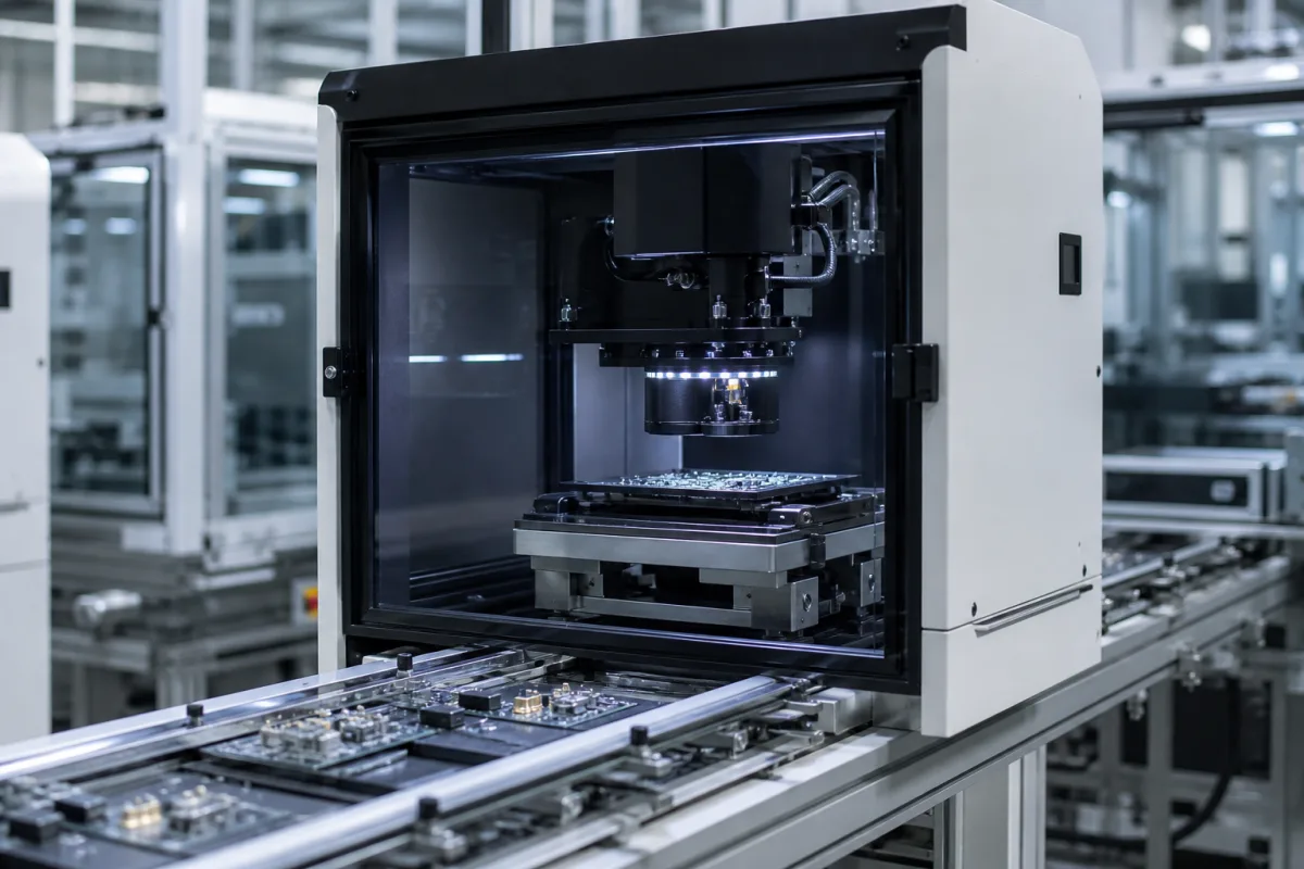
Optical 3D scanner for dimensional inspection (handheld laser and fixed blue-light scanners)
Optical 3D scanners for dimensional inspection · accuracy and volumetric accuracy by part size, acceptance test, working distance, laser line and blue-light types
An optical 3D scanner for dimensional inspection captures the surface of a part as a dense point cloud or mesh using laser lines or projected blue light and cameras, so it can be compared with CAD or measured. It may be handheld for large and varied parts or fixed in a cell over the part. Ask three things first: what accuracy the scanner holds over the size of your parts, which acceptance test and working distance the figures were measured at, and which software and output formats carry the data into your inspection.
Optical 3D scanners for measuring and inspecting parts: handheld laser-line scanners and fixed structured or blue-light scanners, with their software. Barcode scanners are covered on the Barcode scanner page; terrestrial survey lidar, safety laser scanners, laser galvanometer scanners and printer laser units are outside this page.
CNFX editorial research · Sources checked October 12, 2026 · 3 sources
Creaform's technical specifications for its HandySCAN BLACK Elite list an accuracy of 0.025 mm and a volumetric accuracy, based on part size, of 0.020 mm + 0.040 mm/m, with an acceptance test based on VDI/VDE 2634 part 3, and state that this acceptance test is ISO 17025 accredited and each scanner is delivered with a personalized certificate. Measurement capabilities are given at a working distance of 0.3 m: pin 0.750 mm, hole 1.250 mm, step 0.025 mm and wall 0.500 mm, with 0.025 mm measurement resolution and 0.100 mm mesh resolution. [1]
Its HandySCAN EVO series table shows how the figure changes within one range: 0.025 mm accuracy and 0.020 mm + 0.040 mm/m on the first two models, and down to 0.015 mm and 0.015 mm + 0.015 mm/m on the top model, figures the table ties to footnoted options; the top model's acceptance test is listed as based on ISO 10360 rather than VDI/VDE 2634 part 3, and it lists sphere and flat form errors of 0.030 mm and 0.050 mm. [2]
Editorial calculation: a volumetric accuracy of 0.020 mm + 0.040 mm/m gives 0.020 + 0.040 × 1 = 0.060 mm over a 1 m part and 0.020 + 0.040 × 4 = 0.180 mm over the 4 m upper end of the recommended part size, against 0.015 + 0.015 × 1 = 0.030 mm at 1 m for the top EVO model; compare these with the tolerance you need to check, and ask which test standard each figure comes from. [1][2]
Give the supplier the parts (sizes, materials, surface finish and colour), features and tolerances to check, handheld or fixed use, working space, required accuracy over the part size and its test basis, measurement rate, software and CAD comparison needs, output formats, operator training and quantity.
02
Match working distance, range and scanner type to the setup
Creaform lists its laser-line scanners with 22, 30 or 46 blue laser lines (each plus one extra line), measurement rates of 1,300,000, 1,800,000 and 2,800,000 measurements per second, working distances of 200 to 450 mm or 200 to 750 mm, depths of field of 250 mm or 550 mm, a recommended part size of 0.05 to 4 m, and output to formats including .stl, .obj and .ply with compatibility with inspection packages such as PolyWorks and Geomagic. [2]
STScan lists fixed blue-light scanners for inspection and reverse engineering: the T500 single-range scanner and a multi-range system configurable with up to three of its 5x, 10x, 20x, 30x, 40x and 50x scanning ranges, and claims accuracy of up to 0.005 mm, which is the maker's own figure. [3] Editorial note: ask a fixed-scanner supplier for its accuracy statement in the same form as a handheld one, with the measuring volume, test standard and conditions, before comparing a single number.
03
STScan blue-light and SingularXYZ handheld laser scanners
STScan lists blue-light industrial 3D scanners for measurement and inspection; SingularXYZ lists H1 and H2 handheld 3D laser scanners in its geospatial range. Ask each for accuracy over your part size, its test basis and the software supplied.
04
Light source, cameras, calibration, positioning and software
One maker delivers each scanner with a personalized certificate from an ISO 17025 accredited acceptance test; ask how frames are positioned against each other for your part size.
Measurement resolution, points per second and working distance for 3D scanners
The dpi, ppm and colour-depth field names come from 2D scanners; for 3D scanners read them as measurement resolution, measurements per second and working distance.
Field
What it means and published values
Ask the supplier for
Optical resolution (dpi)
For 3D scanners stated as measurement resolution; example 0.025 mm. [1]
Resolution in mm.
Scan speed (ppm)
Stated as measurements per second; examples 1.3-2.8 million. [2]
Rate and frame speed.
Scan area (mm)
Working distance 200-750 mm; part size 0.05-4 m. [2]
Measuring volume.
Color depth (bit)
Colour capture where offered.
Colour option.
Optical density (D)
Applies to document scanners, not 3D scanners.
N/A.
Interface
Connection to the computer.
Interface.
Power consumption (W)
Scanner and computer.
Power.
Operating temperature (°C)
Conditions for the stated accuracy.
Range.
Humidity (%RH)
Operating conditions.
Range.
Ingress protection
Shop-floor use.
Rating.
Weight (kg)
Handheld comfort or mounting.
Weight.
06
Send the part, tolerance and workflow data together
Paste it into your enquiry below or into an email to a maker, then replace every bracket.
Explore company information and manufacturing capabilities, then discuss the scope of your project with a relevant supplier.
Share this page
Compiled and source-reviewed by the CNFX editorial team.
Each manufacturer above links to the page on that company's own website where the product is listed, with the date we checked it. How we source and review
· Page last updated 13 October 2026
Buyer questions
What does volumetric accuracy mean on a 3D scanner?
Creaform states it based on part size, for example 0.020 mm + 0.040 mm/m, so the allowed error grows with the length measured. [1]
Which standard do 3D scanner acceptance tests use?
Creaform lists acceptance tests based on VDI/VDE 2634 part 3 for some models and ISO 10360 for its top EVO model. [1][2]
How fast do handheld laser scanners measure?
Creaform lists 1,300,000 to 2,800,000 measurements per second across its EVO models. [2]
What is a multi-range blue-light scanner?
STScan lists a system configurable with up to three scanning ranges from 5x to 50x for different part sizes. [3]
Sources and what still needs a direct check
Sources checked 2026-10-12. Creaform publishes specifications for its own handheld scanners; STScan describes its own blue-light scanners. Figures are the makers' own.