Editorial Technical Reference

Optocoupler / Isolation Circuit

This page explains how Optocoupler / Isolation Circuit is classified within Computer, Electronic and Optical Product Manufacturing. Technical values and manufacturer relationships are research references; confirm the current specification and supplier evidence for each order.

Technical Definition & Core Assembly

An electronic component that transfers electrical signals between two isolated circuits using light, providing electrical isolation and noise immunity.
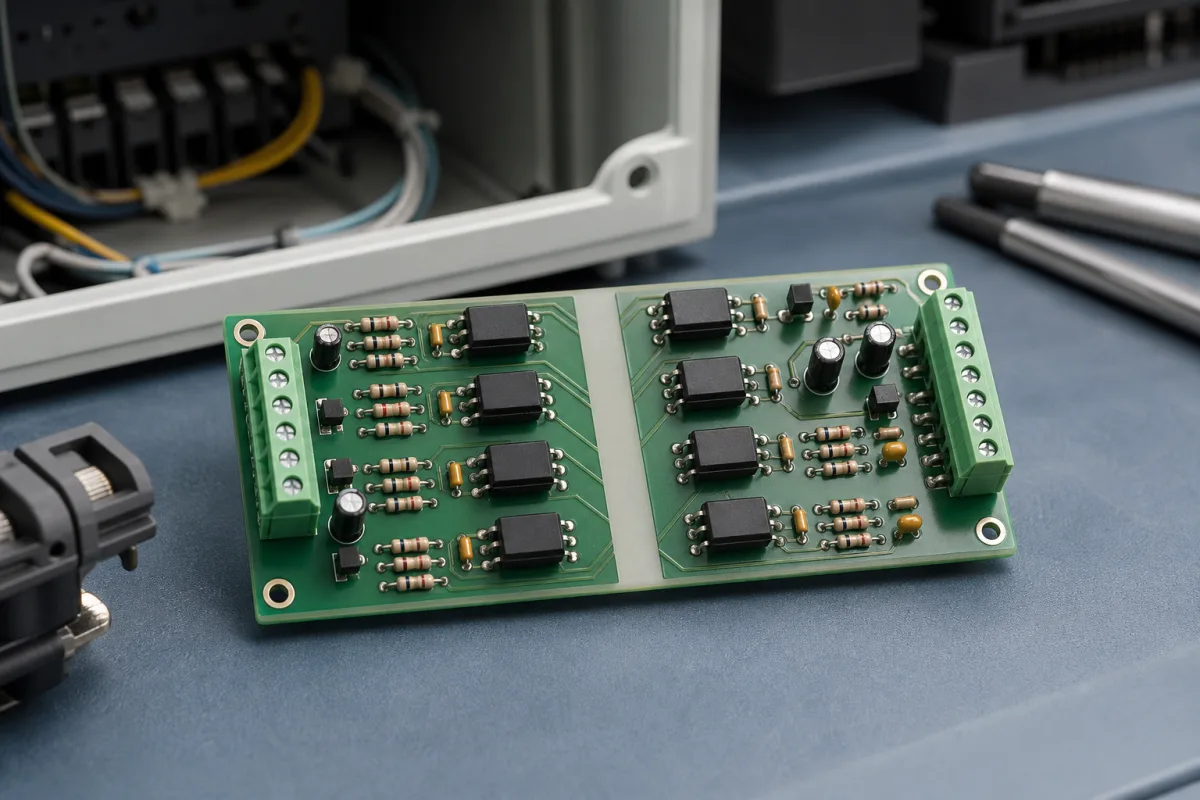
Representative product image. Confirm appearance and specifications with the manufacturer.

Product Specifications

Technical details and manufacturing context for Optocoupler / Isolation Circuit

Definition
Within Input/Output Modules, the optocoupler/isolation circuit serves as a critical interface component that electrically isolates the sensitive control circuitry (e.g., PLC, microcontroller) from potentially noisy, high-voltage, or different ground potential field devices. It prevents ground loops, suppresses electrical noise, and protects the control system from voltage spikes and transients originating in the industrial environment. The component consists of an input side with a light-emitting diode (LED) and an output side with a photosensitive detector, such as a phototransistor or photodiode, housed in a plastic or ceramic package. The isolation barrier provides galvanic isolation, meaning no electrical current flows between the input and output, only light. This design ensures that voltage differences, noise, and transients on the field side do not affect the control side. Key parameters include isolation voltage (3750–5000 Vrms per IEC 60747-5-5), current transfer ratio (50–600% at IF=5mA, VCE=5V), collector-emitter saturation voltage (0.1–0.4 V), input forward voltage (1.2–1.5 V at IF=10mA), bandwidth (0.1–10 MHz), propagation delay (0.1–10 µs), operating temperature range (-40–85 °C), creepage distance (7–10 mm per IEC 60664-1), package types (DIP-4, SOP-4, SMD-4), maximum input current (50–60 mA), output collector current (50–100 mA), and isolation resistance (10^10–10^12 Ω at 500V DC). These values are typical ranges; actual specifications must be confirmed with the manufacturer for the specific model. The optocoupler is used in industrial automation, motor drives, power supplies, and communication interfaces to ensure safe and reliable signal transfer. It is essential for maintaining signal integrity and protecting sensitive electronics from harsh industrial conditions. Always verify model-specific data and standards compliance with the legal manufacturer or supplier before procurement.
Working Principle
An input electrical signal drives an internal light-emitting diode (LED). The emitted light is detected by a photosensitive component (e.g., phototransistor, photodiode, or photo-triac) on the isolated output side, which regenerates the electrical signal. This light-based transfer provides complete galvanic isolation between the input and output circuits. The LED converts the input current into light, which is then converted back into an electrical signal by the detector. The isolation barrier prevents any direct electrical connection, ensuring that voltage spikes, noise, and ground potential differences do not propagate across the barrier. The current transfer ratio (CTR) indicates the efficiency of signal transfer, and the propagation delay affects timing in control loops. The component operates within specified voltage, current, and temperature limits to maintain reliable isolation and signal integrity.
Common Materials
Gallium Arsenide (GaAs) LED, Silicon Phototransistor/Photodiode, Plastic or Ceramic Package
Technical Parameters
ParameterTypical rangeNotes & selection driver
Isolation Voltage3750–5000 VrmsMinimum for reinforced insulation in mains applicationsIEC 60747-5-5
Current Transfer Ratio50–600 %At IF=5mA, VCE=5V; affects output drive capabilityIEC 60747-5-5
Collector-Emitter Saturation Voltage0.1–0.4 VLow VCE(sat) reduces power dissipationIEC 60747-5-5
Input Forward Voltage1.2–1.5 VTypical for GaAs LED at IF=10mAIEC 60747-5-5
Bandwidth0.1–10 MHzFor digital signals; higher for high-speed optocouplers
Propagation Delay0.1–10 µsCritical for timing in control loops
Operating Temperature Range-40–85 °CExtended range available for automotiveIEC 60747-5-5
Creepage Distance7–10 mmFor reinforced insulation in pollution degree 2IEC 60664-1
Package TypeDIP-4, SOP-4, SMD-4DIP for through-hole, SOP/SMD for surface mount
Input Current (Max)50–60 mAAbsolute maximum rating; derate at high temperature
Output Collector Current50–100 mAMaximum continuous current through output transistor
Isolation Resistance10^10–10^12 ΩAt 500V DC; high resistance ensures isolation integrityIEC 60747-5-5

Ranges are indicative industry figures for RFQ preparation, not a supplier commitment. Confirm every value and standard with the legal manufacturer before ordering.

Components / BOM
  • Light-Emitting Diode (LED) Part
    Converts the input electrical signal into infrared light.
    Material: Gallium Arsenide (GaAs) semiconductor
  • Photosensitive Detector Part
    Detects the emitted light and converts it back into an electrical signal on the output side.
    Material: Silicon semiconductor (e.g., phototransistor, photodiode)
  • Isolation Barrier
    Provides the physical dielectric separation (e.g., air gap, transparent insulation) between the LED and detector, enabling high-voltage isolation.
    Material: Transparent molding compound (e.g., silicone, epoxy) or ceramic

Applied To / Applications

This component is essential for the following industrial systems and equipment:

Industrial Ecosystem & Supply Chain Structure

Complementary Systems
Downstream Applications
Specialized Tooling

Application Fit & Sizing Matrix

Operational Limits
voltage: Up to 5000Vrms isolation voltage
temperature: -40°C to +125°C (operating range)
switching speed: Up to 50MHz for high-speed variants
current transfer ratio: 20% to 600% depending on model
Media Compatibility
✓ Industrial control systems ✓ Medical equipment requiring patient isolation ✓ Power supply feedback circuits
Unsuitable: Direct exposure to high-intensity UV/IR light sources that could saturate the photodetector
Sizing Data Required
  • Required isolation voltage rating
  • Signal frequency/bandwidth requirements
  • Input current/forward voltage for LED side

Reliability & Engineering Risk Analysis

Failure Mode & Root Cause
LED Degradation
Cause: Thermal stress from overcurrent or high ambient temperatures causing reduced light output over time
Phototransistor Failure
Cause: Electrostatic discharge (ESD) or voltage transients damaging the semiconductor junction
Maintenance Indicators
  • Inconsistent or erratic signal transmission in the circuit
  • Visible physical damage such as cracks or discoloration in the optocoupler package
Engineering Tips
  • Implement proper current limiting and thermal management to prevent LED overheating
  • Use ESD protection and transient voltage suppression on input/output lines

Indicative industry ranges for design and RFQ preparation. Confirm the exact figures and applicable standard with the manufacturer before specifying.

Compliance & Manufacturing Standards

Applicable Standards
ANSI/UL 1577 - Standard for Optically Isolated Couplers IEC 60747-5-5 - Semiconductor devices - Optoelectronic devices - Photocouplers

Quoted from the published standard.

Manufacturing Precision
  • Isolation Voltage: +/-10% of rated value
  • Current Transfer Ratio (CTR): +/-20% at specified conditions
Quality Inspection
  • High-Potential (Hi-Pot) Test for dielectric strength
  • Current Transfer Ratio (CTR) measurement at operating conditions

Manufacturers of Optocoupler / Isolation Circuit

Manufacturer profiles associated with Optocoupler / Isolation Circuit.

Sourcing Optocoupler / Isolation Circuit from China?
Tell us your specification and target quantity — we will match it against manufacturer records and come back with the factories that fit.
Request manufacturers We manufacture this

Manufacturer listings support early research and capability understanding. They are not certification, ranking, or transaction guarantees.

Technical documentation
Request current drawings, revision history, and a signed specification sheet.
Manufacturing capability
Verify equipment lists, process limits, capacity, and representative production evidence.
Inspection readiness
Confirm test methods, calibrated equipment, sampling plans, and traceable reports.
Supplier transparency
Check the legal entity, factory address, ownership, certifications, and direct contacts.

CNFX does not score or rank suppliers. Buyers must verify all claims and documents with the legal manufacturer before ordering.

Supply Chain Compatible Machinery & Devices

Industrial Smart Camera Module

The Industrial Smart Camera Module is a compact, self-contained vision processing unit designed for integration into industrial machinery and production lines.

Explore Specs →
Surface Mount Resistor

Passive electronic component for current limiting and voltage division in circuits

Explore Specs →
Surface Mount Capacitor

A surface mount capacitor is a fundamental electronic component used for energy storage, filtering, coupling, and decoupling in electronic circuits.

Explore Specs →
Surface Mount Technology (SMT) Pick-and-Place Machine

Automated machine that precisely places electronic components onto printed circuit boards.

Explore Specs →

Frequently Asked Questions

What is the purpose of an optocoupler in an I/O module?

It electrically isolates the control circuitry from field devices, preventing ground loops, suppressing noise, and protecting against voltage spikes and transients.

What are typical isolation voltage ratings?

Typical isolation voltage ranges from 3750 to 5000 Vrms, as per IEC 60747-5-5, but actual ratings depend on the specific model and must be confirmed with the manufacturer.

How does the current transfer ratio (CTR) affect performance?

CTR indicates the efficiency of signal transfer from input to output. A higher CTR means better output drive capability, but it varies with operating conditions and must be verified for the application.

What package types are available?

Common package types include DIP-4 for through-hole mounting and SOP-4 or SMD-4 for surface mount. The choice depends on the PCB design and assembly process.

Data Basis

Editorial classification, named public sources where available, and source-reviewed manufacturer records.

Preliminary Technical Classification
This page supports structured research, RFQ preparation, and supplier evaluation. It does not replace buyer-led supplier qualification, standards review, or technical approval.
Buyer enquiry

Request manufacturing insight for Optocoupler / Isolation Circuit

Ask for use case, specification boundaries, supplier type, and RFQ preparation information for this product.

Where it goes
Straight to the CNFX editorial desk, and to the manufacturer if this product is linked to a claimed profile. Nothing is broadcast to a supplier list.
Your details stay here
We do not sell or rent enquiry data, and we do not add you to a mailing list. Used only to answer this request.
No commission, no middleman
CNFX is a directory. We take no cut of any order and never negotiate on a supplier's behalf.
What we don't claim
A listing is not an endorsement. Qualify every supplier and verify every figure yourself before ordering.

Your business information is used only to process this request.

Thank you! Your message has been sent. We'll respond within 1–3 business days.
Sorry, we couldn't send your message. Please try again, or email us at contact@cnfx.com.

Need to Manufacture Optocoupler / Isolation Circuit?

Compare manufacturer profiles with relevant product and process capability.

Previous Product
Optical Silicone Rubber
Next Product
Oscillator IC / Amplifier Circuit
Get QuotesChat