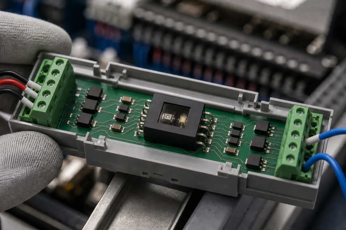
Optocouplers and signal isolators · LED-to-phototransistor coupling, current transfer ratio, isolation test voltage, creepage and clearance, coupling capacitance and common-mode rejection, switching speed, and capacitive digital isolators as the high-speed alternative
An optocoupler (opto-isolator, photocoupler) passes a signal across an insulation barrier as light: an LED on the input side drives a photodetector on the output side, so control and load circuits stay galvanically isolated. Capacitive digital isolators do the same job electrically for fast data. Ask three things first: what isolation voltage and safety approvals the barrier needs, what current transfer ratio or data rate the signal needs, and how much common-mode noise it must reject.
Phototransistor, photodarlington, logic-output and photo-triac optocouplers and integrated digital isolators used for signal isolation in power supplies, motor drives, industrial I/O and medical equipment. Solid-state relays (a separate product page), isolated DC-DC converters and isolation amplifiers sold as such are outside this page except where compared.
CNFX editorial research · Sources checked October 12, 2026 · 5 sources
Vishay's general description explains that the control circuit is on the emitter side and the load circuit on the detector side, with signals transmitted optically from DC up to the MHz band, “in most cases” by light whose wavelengths span the red to infrared range; compared with relays, optocouplers offer smaller size, shorter switching times and no contact bounce or arcing, and, in Vishay's words, they “are used to an increasing extent as safety tested components, e.g., in switch mode power supplies”. It lists high current transfer ratio (CTR) and low degradation among the essential requirements. [1] Its 4N25 family pairs a gallium arsenide infrared LED with a silicon NPN phototransistor in a 6-pin DIP; the DC CTR at VCE = 10 V and IF = 10 mA is 20% minimum and 50% (typ.) for the 4N25 and 4N26, and 10% minimum for the 4N27 and 4N28; rise and fall times are 2 µs at IF = 10 mA and RL = 100 Ω; and the LED is rated 60 mA forward current with a 5 V reverse voltage. [2]
Editorial calculation: with the 4N25's minimum CTR of 20%, 10 mA of LED current guarantees at least 0.2 × 10 = 2 mA of collector current. To pull a 5 V output low through a collector resistor, that resistor must be at least about 5 / 0.002 = 2.5 kΩ (ignoring the saturation voltage); using the 50% (typ.) CTR from the data sheet instead would under-design the circuit as the LED ages. The supply and LED current are assumed examples.
Give the supplier the input drive current and voltage, output type (phototransistor, Darlington, logic, triac or digital isolator), minimum CTR or data rate, switching time or propagation delay, isolation test voltage and working voltage, creepage and clearance, safety approvals (UL 1577, VDE), common-mode transient immunity, channel count, package, temperature range and lifetime or degradation requirements.
02
Specify the isolation barrier and noise rejection
The 4N25 data sheet lists an isolation test voltage of 5,000 V rms, creepage and clearance of at least 7 mm, isolation thickness between emitter and detector of at least 0.4 mm, a comparative tracking index of 175, isolation resistance of 10¹² Ω at 25 °C, coupling capacitance under 0.5 pF, operation from −55 to +100 °C and UL 1577 approval. [2] Vishay notes that low coupling capacitance suppresses interference spikes from steep pulse edges crossing the barrier, which is what is meant by common-mode rejection. [1] TI's ISO774x quad-channel digital isolators, which use a double capacitive silicon dioxide barrier, list 100 Mbps data rate, 10.7 ns propagation delay (typ.) at 5 V, up to 5,000 V rms isolation, ±100 kV/µs common-mode transient immunity (typ.), a projected lifetime of over 30 years at 1,500 V rms working voltage and certification to DIN EN IEC 60747-17 and UL 1577. [3]
Editorial calculation: a 2 µs rise time limits a phototransistor optocoupler to roughly 1 / (2 × 2 µs) ≈ 250 kHz for a square wave with equal rise and fall, before allowing any time at the logic levels, while a 100 Mbps digital isolator handles signals hundreds of times faster. The comparison is approximate; check the data rate in the actual circuit.
03
Name the right IEC component standard for optocouplers
Photocouplers (optocouplers) have their own IEC component standard, separate from the IEC 60747-17 standard that the ISO774x digital isolators above are certified to. IEC 60747-5-5 specifies the terminology, essential ratings, characteristics, safety tests and measuring methods for photocouplers. Its first edition (26 September 2007) replaced the photocoupler clauses of IEC 60747-5-1, 5-2 and 5-3 and stated that photocouplers certified to those earlier parts are to be considered compliant; it was withdrawn on 20 July 2020 when the second edition was published. The 2020 edition added an optional data-sheet basic insulation rating in accordance with IEC 60664-1:2007, 6.1.3.5, corrected the use of VIORM, and added an alternative surge-pulse (VIOSM) test method. [4][5]
Ask which edition a part's certificate cites: a phototransistor optocoupler such as the 4N25 falls within the photocoupler scope of 60747-5-5, while TI certifies the ISO774x digital isolators to 60747-17. [2][3][1]
Editorial calculation: edition 1 was current for almost 13 years (September 2007 to July 2020).
IEC 60747-5-5 point
Value
Scope
Terminology, ratings, characteristics, safety tests, measuring methods for photocouplers
Edition 1
26 September 2007; replaced 60747-5-1/-2/-3 photocoupler clauses; withdrawn 20 July 2020
Edition 2
Published 20 July 2020
New in ed. 2
Optional basic insulation rating per IEC 60664-1:2007 6.1.3.5; VIORM corrections; alternative VIOSM surge test
Digital isolators
Covered separately by IEC 60747-17 (see above)
Ask the supplier for the certificate number and the standard edition for the reinforced-insulation rating (VIORM, VIOTM, VIOSM), and whether the data sheet uses the optional basic insulation rating of the 2020 edition.
04
Phototransistor optocouplers or capacitive digital isolators, and the listed optocoupler maker
Orient Components lists phototransistor optocouplers alongside Darlington, triac, high-speed isolation and IGBT gate-drive optocouplers; the two device types below come from the Vishay and TI data sheets.
Types include phototransistor optocouplers with base connection such as the 4N25 family, and integrated digital isolators with capacitive barriers for multi-channel, high-speed data. [2][3]
05
Input LED, photodetector, insulation barrier, package and capacitive barrier
The last row is the digital-isolator alternative: TI's ISO774x replaces the LED and phototransistor with a double capacitive silicon dioxide barrier. [3]
1 company lists this product among what they make. Company figures are quoted from each
company's own website; every card states where the relationship came from.
Explore company information and manufacturing capabilities, then discuss the scope of your project with a relevant supplier.
Share this page
Compiled and source-reviewed by the CNFX editorial team.
Each manufacturer above links to the page on that company's own website where the product is listed, with the date we checked it. How we source and review
· Page last updated 13 October 2026
Buyer questions
What is current transfer ratio?
The ratio of output collector current to LED input current; Vishay's 4N25 is specified at 20% minimum and 50% (typ.) at 10 mA. [2]
How much voltage can an optocoupler isolate?
The 4N25 is rated for a 5,000 V rms isolation test voltage with at least 7 mm creepage and clearance. [2]
When should a digital isolator replace an optocoupler?
For fast data: TI's ISO774x reach 100 Mbps with a 10.7 ns delay (typ.), against 2 µs rise times for a phototransistor optocoupler. [3][2]
Which IEC standard covers optocouplers?
IEC 60747-5-5 covers photocouplers (optocouplers); its second edition was published on 20 July 2020 and added an optional basic insulation rating and an alternative VIOSM surge test. [4]
Sources and what still needs a direct check
Sources checked 2026-10-12. Vishay and Texas Instruments are semiconductor makers describing their own devices; their figures are examples, not limits for other parts. The two IEC 60747-5-5 entries are Standard Norge abstracts of the 2007 and 2020 editions.