Editorial Technical Reference

Input/Output Modules

This page explains how Input/Output Modules is classified within Machinery and Equipment Manufacturing. Technical values and manufacturer relationships are research references; confirm the current specification and supplier evidence for each order.

Technical Definition & Core Assembly

Electronic interface units that connect PLCs to external sensors, actuators, and devices by converting signals between the digital/analog domains.
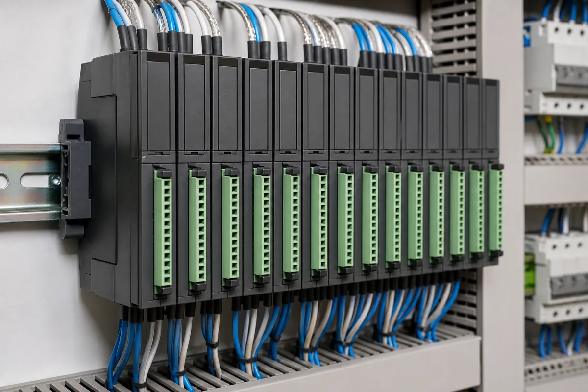
Representative product image. Confirm appearance and specifications with the manufacturer.

Product Specifications

Technical details and manufacturing context for Input/Output Modules

Definition
Input/Output (I/O) Modules are critical hardware components within a Programmable Logic Controller (PLC) system. They serve as the physical interface between the PLC's central processing unit (CPU) and the external industrial environment. Input modules receive signals from sensors (e.g., limit switches, temperature sensors, pressure transducers) and convert them into digital or analog data the CPU can process. Output modules receive commands from the CPU and convert them into signals capable of controlling actuators (e.g., motor starters, solenoid valves, indicator lights). They provide electrical isolation, signal conditioning, and protection for the sensitive PLC electronics. These modules are typically mounted on a DIN rail or in a chassis and communicate with the CPU via a backplane bus or fieldbus network. The number of channels per module varies, and the specific configuration must be selected based on the application's requirements. I/O modules are available in various forms, including discrete (on/off) and analog (continuous) types, and may support different voltage and current levels. They are designed to withstand industrial environments, with features such as surge protection and noise immunity. When selecting I/O modules, it is essential to verify compatibility with the PLC model, the required number of channels, signal types, and isolation requirements. Always consult the manufacturer's documentation for specific ratings and installation guidelines. Regular maintenance includes checking for loose connections, inspecting for damage, and verifying proper operation. Failure of an I/O module can result in loss of control or incorrect process readings, so timely replacement is critical. For detailed specifications and standards compliance, refer to the original equipment manufacturer.
Working Principle
I/O modules operate on signal conversion and electrical isolation principles. Input modules typically use optocouplers or isolation amplifiers to receive varying voltage/current signals from field devices, condition them (e.g., filtering, scaling), and present a clean digital or analog value to the PLC's backplane bus. Output modules receive digital commands or analog setpoints from the CPU via the bus, use driver circuits (like transistors or relays) to amplify the signal, and deliver the appropriate power level (voltage/current) to the connected actuator. Communication with the CPU is managed through a standardized backplane or network protocol.
Common Materials
Printed Circuit Board (PCB), Semiconductors (ICs, transistors, optocouplers), Connectors (terminal blocks, headers), Plastic/Polycarbonate Housing
Technical Parameters

What to specify in your RFQ

  • Number of discrete or analog input/output points per module. in Channels

These are the quantities to specify to the manufacturer when sizing or requesting a quote. The manufacturer's own documentation governs the exact figures and applicable standard.

Components / BOM
  • Terminal Block
    Provides secure screw or spring-clamp connections for field wiring from sensors and actuators.
    Material: Plastic (housing), Copper alloy (terminals)
  • Optocoupler / Isolation Circuit
    Provides electrical isolation between the field-side wiring and the internal logic circuits to protect the PLC from voltage spikes and noise.
    Material: Semiconductor materials (LED, phototransistor/photodiode)
  • Signal Conditioning Circuitry
    Filters, amplifies, scales, or converts incoming/outgoing analog or digital signals to appropriate levels for the CPU or field devices.
    Material: Resistors, capacitors, operational amplifiers (ICs) on PCB
  • Communication Interface Chip Part
    Manages data exchange between the module and the PLC CPU via the backplane or network protocol.
    Material: Integrated Circuit (IC)
  • Status Indicators (LEDs) Part
    Visual indicators showing power status, communication activity, and per-channel I/O state (on/off, fault).
    Material: LEDs, plastic lenses
  • Output Driver Circuit
    Amplifies the CPU's command to the power level the field actuator needs.

Applied To / Applications

This component is essential for the following industrial systems and equipment:

Industrial Ecosystem & Supply Chain Structure

Complementary Systems
Downstream Applications
Specialized Tooling

Application Fit & Sizing Matrix

Operational Limits
pressure: Not applicable (electronic module)
other spec: Signal types: 0-10V, 0-20mA, 4-20mA, 24VDC digital, 120VAC digital; Isolation voltage: 500-1500V; Sampling rate: 10-1000 Hz
temperature: -20°C to +70°C (operating), -40°C to +85°C (storage)
Media Compatibility
✓ Industrial control cabinets (IP20 rated) ✓ Process control panels with DIN rail mounting ✓ Factory automation environments with EMC protection
Unsuitable: Outdoor environments without proper IP67+ enclosure protection
Sizing Data Required
  • Number and type of I/O points required (digital/analog)
  • Communication protocol compatibility (Profibus, Ethernet/IP, Modbus, etc.)
  • Power supply requirements and backplane current consumption

Reliability & Engineering Risk Analysis

Failure Mode & Root Cause
Contact corrosion
Cause: Exposure to moisture, corrosive atmospheres, or incompatible materials leading to oxidation and poor electrical connectivity.
Signal drift or loss
Cause: Component aging, thermal stress, or electromagnetic interference degrading signal integrity over time.
Maintenance Indicators
  • Intermittent or erratic signal behavior indicating loose connections or failing components
  • Unusual heat emission from module housing suggesting overload or short-circuit conditions
Engineering Tips
  • Implement regular environmental monitoring and sealing to prevent moisture ingress and corrosion
  • Schedule periodic calibration and signal integrity testing to detect and correct drift before failure

Indicative industry ranges for design and RFQ preparation. Confirm the exact figures and applicable standard with the manufacturer before specifying.

Compliance & Manufacturing Standards

Applicable Standards
IEC 61131-2: Programmable controllers - Part 2: Equipment requirements and tests UL 508: Standard for Industrial Control Equipment EN 61000-6-2: Electromagnetic compatibility (EMC) - Part 6-2: Generic standards - Immunity standard for industrial environments

Quoted from the published standard.

Manufacturing Precision
  • Connector Pin Alignment: +/-0.15mm
  • Signal Timing Accuracy: +/-0.5% of full scale
Quality Inspection
  • High Potential (Hi-Pot) Dielectric Strength Test
  • Environmental Stress Screening (ESS) including thermal cycling and vibration testing

Manufacturers of Input/Output Modules

Manufacturer profiles associated with Input/Output Modules.

Sourcing Input/Output Modules from China?
Tell us your specification and target quantity — we will match it against manufacturer records and come back with the factories that fit.
Request manufacturers We manufacture this

Manufacturer listings support early research and capability understanding. They are not certification, ranking, or transaction guarantees.

Technical documentation
Request current drawings, revision history, and a signed specification sheet.
Manufacturing capability
Verify equipment lists, process limits, capacity, and representative production evidence.
Inspection readiness
Confirm test methods, calibrated equipment, sampling plans, and traceable reports.
Supplier transparency
Check the legal entity, factory address, ownership, certifications, and direct contacts.

CNFX does not score or rank suppliers. Buyers must verify all claims and documents with the legal manufacturer before ordering.

Supply Chain Compatible Machinery & Devices

Heavy-Duty CNC Plasma Cutting Machine

The Heavy-Duty CNC Plasma Cutting Machine is a standalone industrial device designed for cutting conductive metals such as steel, stainless steel, aluminum, and copper alloys.

Explore Specs →
Automated Powder Coating System

Integrated industrial system for applying dry powder coatings to metal substrates.

Explore Specs →
Centrifugal Pump Impeller

The centrifugal pump impeller is a critical rotating component that converts mechanical energy from the motor into kinetic energy in fluid systems.

Explore Specs →
High-Precision CNC Laser Cutting Machine

Computer-controlled industrial machine using focused laser beams to cut sheet metal with micron-level accuracy.

Explore Specs →

Frequently Asked Questions

What is the primary function of an I/O module?

An I/O module acts as the interface between a PLC's CPU and external field devices. Input modules convert sensor signals into data the CPU can process, while output modules convert CPU commands into signals that control actuators.

How do I choose the right I/O module for my application?

Consider the PLC model compatibility, required number of channels, signal type (discrete or analog), voltage/current levels, and isolation needs. Always verify these specifications with the manufacturer's documentation.

What are common signs of an I/O module failure?

Symptoms include loss of communication with the PLC, incorrect readings from sensors, actuators not responding, or visible damage like burnt components. Regular inspection and testing can help detect issues early.

Are I/O modules interchangeable between different PLC brands?

No, I/O modules are typically proprietary to the PLC manufacturer or require specific communication protocols. Always use modules that are compatible with your PLC system to ensure proper operation.

Data Basis

Editorial classification, named public sources where available, and source-reviewed manufacturer records.

Preliminary Technical Classification
This page supports structured research, RFQ preparation, and supplier evaluation. It does not replace buyer-led supplier qualification, standards review, or technical approval.
Buyer enquiry

Request manufacturing insight for Input/Output Modules

Ask for use case, specification boundaries, supplier type, and RFQ preparation information for this product.

Where it goes
Straight to the CNFX editorial desk, and to the manufacturer if this product is linked to a claimed profile. Nothing is broadcast to a supplier list.
Your details stay here
We do not sell or rent enquiry data, and we do not add you to a mailing list. Used only to answer this request.
No commission, no middleman
CNFX is a directory. We take no cut of any order and never negotiate on a supplier's behalf.
What we don't claim
A listing is not an endorsement. Qualify every supplier and verify every figure yourself before ordering.

Your business information is used only to process this request.

Thank you! Your message has been sent. We'll respond within 1–3 business days.
Sorry, we couldn't send your message. Please try again, or email us at contact@cnfx.com.

Need to Manufacture Input/Output Modules?

Compare manufacturer profiles with relevant product and process capability.

Previous Product
Z-axis Ram/Spindle
Last Product
Get QuotesChat