FPGA image processing on the board, before the host sees a pixel
A processing board here means a camera-input board whose FPGA works on the image stream itself: demosaicing, filtering, blob analysis or compression run on the card, and only the result goes to the host. Whether such a board is needed comes down to one ratio, the camera data rate against what the host link can sustain, and to what the FPGA can fit. Basler's microEnable IV VD1-CL datasheet and VisualApplets manual and Euresys's JPEG-encoding documentation give the numbers used below.
Covers camera-input boards that process image data on an FPGA: the in-to-out data reduction the board must achieve, on-board JPEG and Bayer processing channels and their pixel-rate limits, FIFO buffering, and FPGA design with graphical operator libraries. Choosing a frame grabber by camera interface, bus bandwidth, I/O and cabling is covered on Frame Grabber (4375); GPU and server sizing for AOI on Image Processing Computer (2927); multi-port GigE PoE boards on Interface Board (5042); vision boxes with strobe outputs on Image Processing Unit (588).
CNFX editorial research · Sources checked October 13, 2026 · 3 sources
850 MB/s in, 200 MB/s out: the board has to shrink the data at least 4.25 times
Basler's microEnable IV VD1-CL is a clear case of a board sold for its processing: Basler describes it as suited to high data input despite its PCIe x1 host link.
With a camera running at the full 850 MB/s, only 200 MB/s can leave the board, so the FPGA must cut the stream by at least 850 ÷ 200 = 4.25 times (Editorial calculation). The VisualApplets manual lists operators that can do this on the card, among them ROI selection, binarization and blob detection [2]; whichever is used has to hold the ratio at the worst-case frame rate, not the average.
The 256 MB buffer bridges bursts but does not change the ratio: at a sustained 650 MB/s surplus it fills in about 0.4 s (256 ÷ 650, Editorial calculation).
microEnable IV VD1-CL
Datasheet value
Camera input
2 × Camera Link (MDR26): 2 × Base, 1 × Medium or 1 × Full incl. 10-tap; up to 85 MHz pixel clock
Camera data bandwidth
850 MB/s
Host link
PCI Express x1 (Gen1), up to 200 MB/s sustainable
Processor
Spartan-3 FPGA XC3S1600E
On-board memory
256 MB DDR-RAM, acquisition and image-processing buffer
Supply
3.3 V, 250 mA and 12 V, 520 mA (about 7.1 W, Editorial calculation)
Operating temperature / MTBF
0–50 °C / 176,000 h
The datasheet figures belong to this board. The ratio method applies to any processing board; the numbers do not.
02
Four on-board JPEG channels at 250 MP/s each against a 1,250 MB/s CXP-12 link
Euresys documents the 4-camera firmware of its Coaxlink Quad CXP-12 JPEG board as four independent channels, each a fixed FPGA pipeline from camera to compressed output.
The channel, not the cable, sets the camera's speed. The board's four connections carry 5,000 MB/s together, 1,250 MB/s each; at one byte per Bayer8 pixel that link could deliver 1,250 Mpixel/s, five times what the encoder processes (Editorial calculation). A 5120 × 3840 camera (19.66 Mpixel) is therefore held to about 12.7 frames/s per channel (Editorial calculation).
The other figures size easily from the same frame. The 512 MB FIFO holds 26 full Bayer8 frames of that size (512 × 10⁶ ÷ 19.66 × 10⁶, Editorial calculation). The 8:1 preview is 640 × 480, 921,600 bytes per frame in RGB8. Twenty lines of a 5120-pixel row are 102,400 pixels, about 0.41 ms at 250 Mpixel/s (Editorial calculation).
Stage in each channel
Euresys specification
Camera interface
1-connection CoaXPress CXP-12 host with PoCXP and triggering; CXP-1 to CXP-12
Acquisition gate
Selects which frames are captured
FIFO buffer
512 MB elastic buffer
Bayer CFA decoder
Bayer8 to RGB8
JPEG encoder
RGB8 to YUV422 front end, baseline ISO/IEC 10918-1; quality 1–100, default 75; latency 20 lines (typ.)
Down-scaler
Reduces RGB8 resolution by 8 in both directions for the preview stream
Limits
Pixel processing up to 250 Mpixel/s; 8-bit Bayer area-scan colour cameras only; 128 × 16 to 5120 × 3840, width and height multiples of 8
JPEG quality 75 is the documented default, not a recommendation for inspection images; check that the compression does not hide the defect sizes the system has to find.
03
Programming the FPGA: more than 200 operators, a pipeline, and the resource ceiling
Fixed pipelines like the JPEG channel are one option. Programmable boards let the user build the processing chain; Basler's VisualApplets is the graphical tool that came pre-licensed with the microEnable IV.
Because the delay after start-up is constant and set by the algorithm, a result or trigger derived in the FPGA follows each frame by the same time. Because complexity is bounded by the FPGA's resources, a design has to be checked with the resource estimator for the exact board before it is committed to; the microEnable IV, for example, carries a Spartan-3 XC3S1600E.
Aspect
What Basler states
Design method
Graphical pipeline of operator modules, filter modules and transport links
Library
More than 200 hardware operators: arithmetic and morphological pixel operators, logic for classification, colour processing, statistics
Examples in the manual
Bayer 3×3 and 5×5 demosaicing, binarization and thresholds, BlobDetector1D/2D, ROI selection
Timing
After start-up, a constant delay set by the processing algorithm (datasheet)
Limit on complexity
The manual names the available FPGA resources as the main limit on design complexity
Checks before build
FPGA resource estimation at design and module level, design rules check, high-level simulation
Ask the board maker for the FPGA device and the logic left free after their own acquisition firmware.
04
What to ask for a vision processing board
Paste it into your enquiry below or into an email to a maker, then replace every bracket.
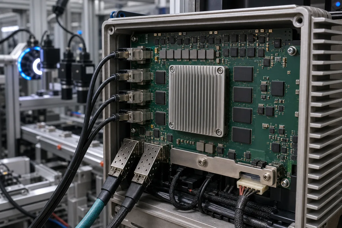
State the camera interface, pixel format, resolution and worst-case frame rate, and what the host should receive (full frames, ROI, compressed images or only results). Ask for the camera data bandwidth, sustained host bandwidth, the on-board memory, the FPGA device and the logic left free for user designs, the processing latency, the programming route (graphical tool, HDL or fixed firmware), power and operating temperature, and how the board's two network or fibre cages, if fitted as in the illustration, are used.
1 company lists this product among what they make. Company figures are quoted from each
company's own website; every card states where the relationship came from.
Cesgate
TBC
Cesgate is a PCB and PCB assembly maker; its product list includes a Signal Processing Board among communication, industrial-control and portable-device boards. No FPGA device, camera interface or image-processing function is published, so it is a route for building a board to the buyer's own design; all specifications TBC, location TBC.
Explore company information and manufacturing capabilities, then discuss the scope of your project with a relevant supplier.
Share this page
Compiled and source-reviewed by the CNFX editorial team.
Each manufacturer above links to the page on that company's own website where the product is listed, with the date we checked it. How we source and review
· Page last updated 13 October 2026
Buyer questions
How do I know whether I need processing on the board?
Divide camera data rate by sustained host bandwidth. Basler's microEnable IV VD1-CL takes 850 MB/s from the camera but sustains 200 MB/s to the host, so at full rate the FPGA must reduce data at least 4.25 times (Editorial calculation). [1]
Does an on-board JPEG encoder limit camera frame rate?
Yes. Euresys's JPEG channels process up to 250 Mpixel/s each, while a CXP-12 connection on the same board carries 1,250 MB/s; a 5120 × 3840 Bayer8 camera is held to about 12.7 frames/s (Editorial calculation). [3]
What does the FIFO on a JPEG channel do?
Euresys fits a 512 MB elastic buffer in each channel ahead of the decoder and encoder, which absorbs bursts; at 5120 × 3840 Bayer8 it holds 26 frames (Editorial calculation). [3]
How is a custom FPGA design built?
With Basler VisualApplets the design is a graphical pipeline drawn from more than 200 hardware operators, checked with resource estimation, design rules and simulation before the build. [2]
Sources and what still needs a direct check
Sources checked 2026-10-13. Two Basler documents for a programmable Camera Link board and its FPGA tool, and Euresys's documentation of a fixed-function CoaXPress JPEG board.