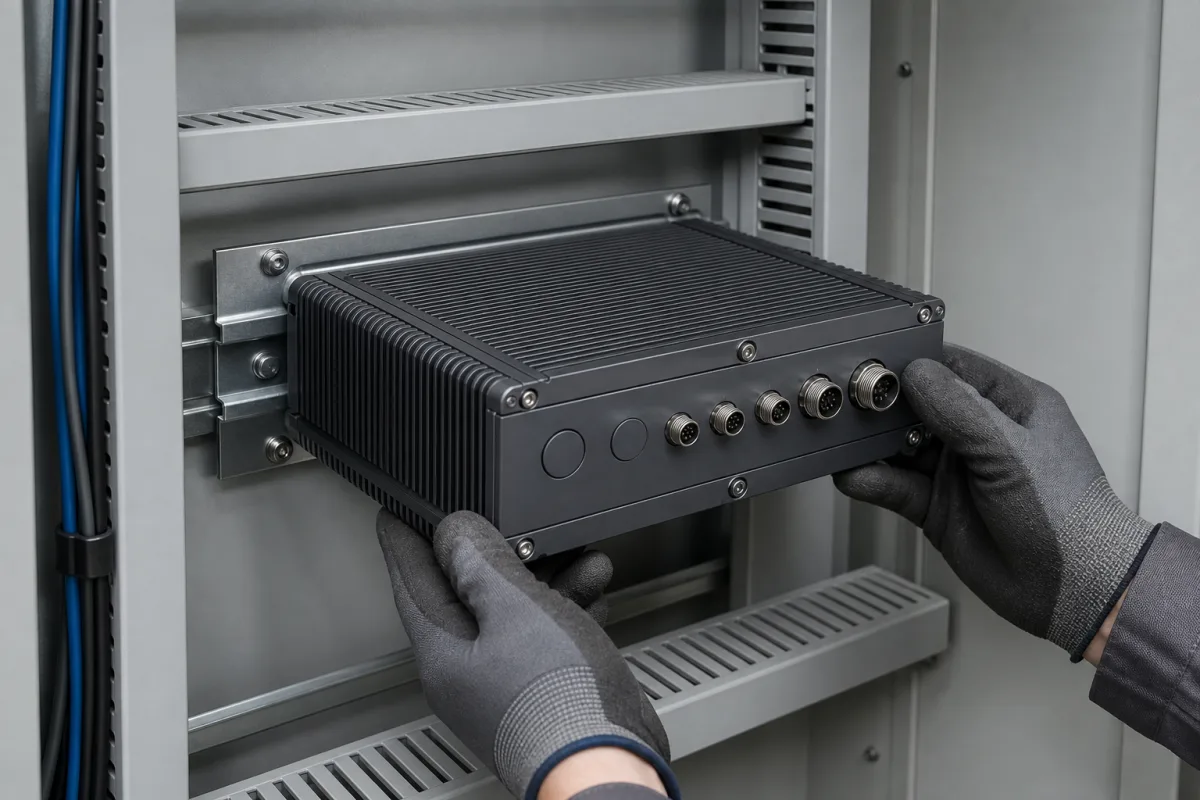
Rolling-stock processing module: a fanless EN 50155 onboard computer fed from the train battery
Onboard processing module for rolling stock · EN 50155 battery voltages and interruption class, OT temperature class, IEC 61373 mounting category, M12 power and Ethernet coding
On a train, the data processing for passenger information, CCTV recording, condition monitoring or the train network sits in a sealed, fanless processing module mounted in an equipment cabinet and powered straight from the vehicle's battery system. What makes it different from a factory box PC is the railway product standard EN 50155: the module has to keep working across the battery voltage band and through short supply interruptions, survive the temperature class of its cabinet and the vibration of the car body, meet railway fire rules, and connect through screw-locking M12 connectors, as both railway computers reviewed on this page do.
Processing modules for railway rolling stock: fanless onboard computers declared to EN 50155 and IEC 61373, fed from the 24 to 110 V vehicle battery supply, with M12 power and network connectors. Microcontroller chips are covered on the Microcontrollers (CPU / MCU) page, and general fanless box PCs for factory and vehicle use on the Embedded computer and Industrial computer pages; modular edge computers, vision processing units and soft-PLC control computers have their own pages. Railway power converters, Ethernet switches and the train's control and management system as a whole are outside this page.
CNFX editorial research · Sources checked October 12, 2026 · 5 sources
Battery voltage band, S2 interruptions and changeover dips the module must ride through
In Bel Fuse's summary of EN 50155:2021, the standard lists nominal battery voltages of 24, 28, 36, 48, 72, 96 and 110 V DC and recommends 24, 72 or 110 V. Equipment must work continuously from 30 % below to 25 % above nominal, withstand ±40 % for 0.1 s and +40 % for 1.0 s, accept a 5 % ripple factor, and ride through a 40 % dip of up to 100 ms during supply changeover. [1]
Editorial calculation from the +25/−30 % band: a 110 V battery system gives 77 to 137.5 V continuous, and 66 to 154 V for the 0.1 s transient; a 24 V system gives 16.8 to 30 V continuous. [1] Advantech states the operating input of an EN 50155 Ethernet switch in exactly that form, 16.8 to 137.5 V DC, for a product sold as 24 to 110 V DC. [3]
Moxa's V2406C railway computer lists its input as 24 to 110 VDC with isolation, on an M12 A-coded male connector, and a maximum power consumption of 70 W. [4] Editorial note: because the Moxa page gives only the nominal span, ask whether the module runs down to 16.8 V on a 24 V battery and up to 137.5 V on a 110 V battery, and which interruption class it was tested to. Advantech's older ITA-5710 is a 24 V DC unit declared to class S2 for interruptions and class C1 for supply changeover, with 48, 72 and 110 V DC inputs as options. [2]
State the vehicle's nominal battery voltage, the interruption class (S1, S2 or S3) and changeover class you need, and ask for the EN 50155 test report covering them; Moxa says its EN 50155 Declaration of Conformity can be requested from Moxa or a distributor. [5]
02
OT temperature class of the cabinet, car-body shock and vibration, and railway fire rating
EN 50155:2017 replaced the earlier temperature classes with six operating temperature classes; Bel Fuse gives the default as OT3 and assigns OT3 and OT4 to equipment in technical cabinets. [1]
Both modules reviewed here are rated −40 to 70 °C in operation and −40 to 85 °C in storage, the OT4 range in Bel Fuse's table. [4][2] Advantech's data sheet adds that the ITA-5710 reaches that range with industrial SSD or CF storage and names it EN 50155 class TX, the pre-2017 designation. [2] The 2017 edition also introduced useful-life classes L1 to L4 of 5 to 20 years, with L4 (20 years) the default unless otherwise specified. [1]
For mechanical stress, EN 50155 refers to EN 61373, which Bel Fuse describes as dividing equipment into body-mounted, bogie-mounted and axle-mounted categories. [1] A processing module in a car-body cabinet falls in the first group: Advantech declares IEC 61373 body mount class B for the ITA-5710, and Moxa lists IEC 61373 for both shock and vibration on the V2406C, together with EN 45545-2 railway fire protection and EN 50121-3-2 and EN 50121-4 for EMC. [2][4] Moxa makes PCB conformal coating available on request and gives an IP20 aluminium housing, so the cabinet, not the module, provides the protection against water and dust. [4]
M12 coding on the module: A-coded power and USB, X-coded or A-coded Ethernet
Advantech describes the M12 connectors on its communication and power ports as ruggedized; the coding of each port decides which cable from the vehicle harness will mate with it. [2]
Advantech sells the mating M12 connectors and short adapter cables, M12 to a two-pin European terminal for power and M12 to RJ45 for LAN, as separate part numbers that must be purchased separately. [2] Editorial note: when the train harness is already terminated, list the coding, pin count and gender of every M12 on the module so that the supplier's adapters or the harness can be matched before delivery.
Explore company information and manufacturing capabilities, then discuss the scope of your project with a relevant supplier.
Share this page
Compiled and source-reviewed by the CNFX editorial team.
Each manufacturer above links to the page on that company's own website where the product is listed, with the date we checked it. How we source and review
· Page last updated 13 October 2026
Buyer questions
What does interruption class S2 mean for an onboard computer?
Per Bel Fuse's summary of EN 50155, an S2 module maintains normal operation through supply interruptions of up to 10 ms and resumes normal operation after longer ones; S2 is the default class. [1]
Which EN 50155 temperature class suits a module in a technical cabinet?
Bel Fuse assigns OT3 (−25 to +70 °C, the default) and OT4 (−40 to +70 °C) to technical cabinets. Moxa and Advantech list −40 to 70 °C for their railway computers. [1][4][2]
What input voltage range should a 24 to 110 V railway module accept?
Editorial calculation with the +25/−30 % continuous band: 16.8 V on a 24 V battery up to 137.5 V on a 110 V battery, the range Advantech states for one EN 50155 switch. [1][3]
Do railway computers use X-coded M12 Ethernet?
Moxa's V2406C uses two M12 X-coded gigabit ports; Advantech's older ITA-5710 uses 8-pin A-coded M12 for gigabit LAN. [4][2]
Sources and what still needs a direct check
Sources checked 2026-10-12. Bel Fuse, a railway power supply maker, summarises EN 50155 classes in a technical paper; the standard itself governs. Advantech and Moxa data are from their own railway product pages and data sheets.