Editorial Technical Reference

Transceiver ICs

This page explains how Transceiver ICs is classified within Computer, Electronic and Optical Product Manufacturing. Technical values and manufacturer relationships are research references; confirm the current specification and supplier evidence for each order.

Technical Definition & Core Assembly

Integrated circuits combining transmitter and receiver functions for data communication
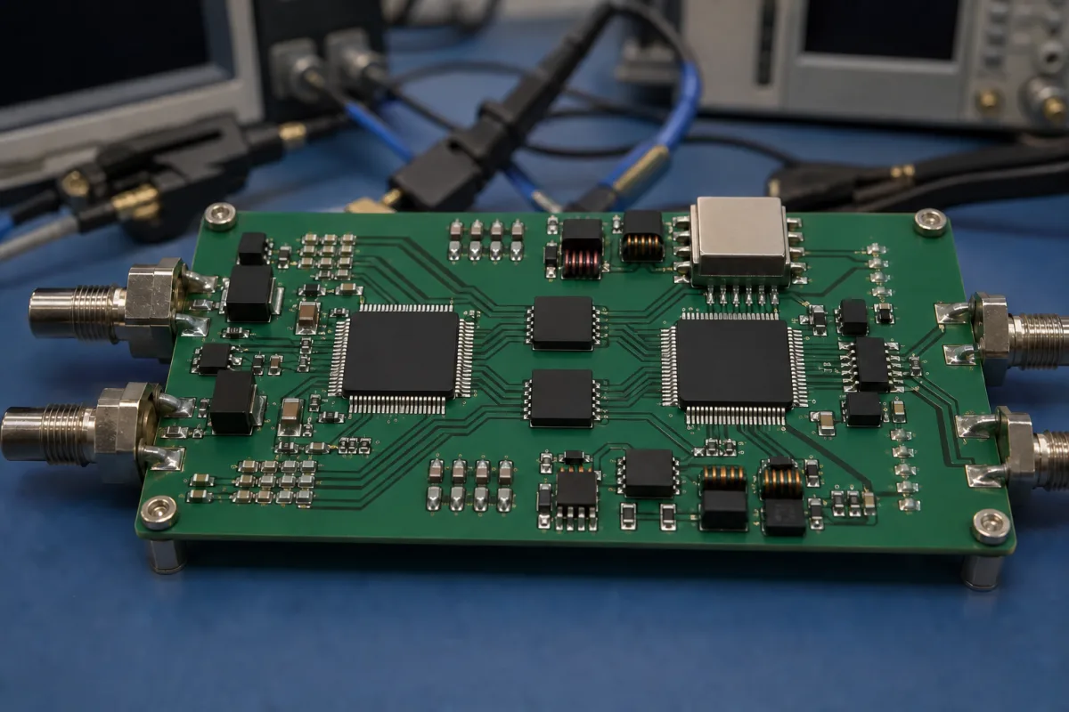
Transceiver ICs in a manufacturing environment
Representative product image. Confirm appearance and specifications with the manufacturer.

Product Specifications

Technical details and manufacturing context for Transceiver ICs

Definition
Transceiver ICs are semiconductor devices integrated onto a single chip that handle both transmission and reception of signals within communication systems. As part of a Communication Interface Board, they serve as the core electronic component responsible for converting, modulating, and demodulating electrical signals to enable reliable data exchange between different devices or systems. These integrated circuits are designed to operate in both directions, managing the physical layer of communication protocols. They typically include analog front-end circuits, digital signal processing blocks, and interface logic to connect with microcontrollers or processors. The materials used in their construction include silicon semiconductor substrates, copper interconnects for electrical routing, gold bonding wires for internal connections, and ceramic or plastic packaging for protection and mounting. Transceiver ICs are characterized by parameters such as data transfer rate, measured in Mbps, which indicates the maximum communication speed they can support. This parameter is a key selection criterion for engineers designing communication interfaces. When selecting a transceiver IC, it is essential to verify the specific data rate requirements of the application, as well as the electrical interface standards (e.g., voltage levels, signaling methods) that must be compatible with the rest of the system. The operating principle involves receiving incoming signals through the receiver section, which amplifies, filters, and demodulates them to extract the original data. Simultaneously, the transmitter section processes outgoing data through modulation, amplification, and signal conditioning before transmission. The IC manages signal timing, protocol handling, and error correction to ensure bidirectional communication integrity. For procurement, it is crucial to confirm the exact model's specifications, including data rate, supply voltage, temperature range, and package type, with the legal manufacturer or supplier. The directory provides reference information only and does not guarantee compliance with any specific standards. Always verify the product's datasheet and relevant industry standards for your application.
Working Principle
Transceiver ICs operate by receiving incoming signals through their receiver section, which typically includes amplification, filtering, and demodulation circuits to extract the original data. Simultaneously, their transmitter section processes outgoing data through modulation, amplification, and signal conditioning before transmission. The IC manages signal timing, protocol handling, and error correction to ensure bidirectional communication integrity.
Common Materials
Silicon semiconductor, Copper interconnects, Gold bonding wires, Ceramic or plastic packaging
Technical Parameters

What to specify in your RFQ

  • Data transfer rate indicating maximum communication speed in Mbps

These are the quantities to specify to the manufacturer when sizing or requesting a quote. The manufacturer's own documentation governs the exact figures and applicable standard.

Components / BOM
  • Transmitter Section
    Converts digital data to modulated electrical signals for transmission
    Material: Silicon semiconductor with copper interconnects
  • Receiver Section
    Receives and demodulates incoming signals to extract digital data
    Material: Silicon semiconductor with gold bonding wires
  • Oscillator Circuit
    Generates precise clock signals for timing synchronization
    Material: Quartz crystal or silicon-based oscillator
  • Power Management Unit Part
    Regulates and distributes power to different sections of the IC
    Material: Silicon semiconductor with copper power rails
  • Protocol and Error Correction Unit
    Handles framing, timing and error correction so the link stays reliable.

Application & selection

Application Fit & Sizing Matrix

Operational Limits
voltage: 1.8V to 3.6V
data rate: Up to 10 Gbps
temperature: -40°C to +125°C
Media Compatibility
✓ Ethernet networks ✓ Fiber optic systems ✓ Wireless base stations
Unsuitable: High-voltage power transmission environments
Sizing Data Required
  • Required data rate (bps)
  • Operating voltage range (V)
  • Interface protocol (e.g., PCIe, USB, SATA)

Risk, maintenance & compliance

Reliability & Engineering Risk Analysis

Failure Mode & Root Cause
Thermal overstress
Cause: Excessive heat generation due to poor thermal management, high ambient temperatures, or inadequate cooling, leading to material degradation, solder joint fatigue, and eventual electrical failure.
Electrostatic discharge (ESD) damage
Cause: Accumulation and sudden discharge of static electricity during handling, installation, or operation, resulting in immediate or latent damage to sensitive semiconductor junctions and internal circuitry.
Maintenance Indicators
  • Intermittent or complete loss of signal transmission/reception despite proper external connections
  • Abnormally high operating temperature detected via thermal imaging or touch, often accompanied by performance degradation
Engineering Tips
  • Implement strict ESD protection protocols during all handling and installation phases, including use of grounded workstations, wrist straps, and anti-static packaging.
  • Ensure optimal thermal design with adequate heat sinking, forced air cooling if necessary, and regular monitoring of operating temperatures to prevent thermal runaway.

Indicative industry ranges for design and RFQ preparation. Confirm the exact figures and applicable standard with the manufacturer before specifying.

Compliance & Manufacturing Standards

Applicable Standards
ANSI/TIA-455-78-C - Fiber Optic Transceiver Testing CE Marking - EMC Directive 2014/30/EU

Quoted from the published standard.

Manufacturing Precision
  • Center Wavelength: +/-0.5 nm
  • Optical Power Output: +/-1.0 dBm
Quality Inspection
  • Bit Error Rate (BER) Test
  • Eye Diagram Analysis
Technical documentation
Request current drawings, revision history, and a signed specification sheet.
Manufacturing capability
Verify equipment lists, process limits, capacity, and representative production evidence.
Inspection readiness
Confirm test methods, calibrated equipment, sampling plans, and traceable reports.
Supplier transparency
Check the legal entity, factory address, ownership, certifications, and direct contacts.

Compare the published product scope and source details, then include your specifications and quantity in an enquiry.

Manufacturers of Transceiver ICs

Manufacturer profiles associated with Transceiver ICs.

Sourcing Transceiver ICs from China?
Tell us your specification and target quantity — we will match it against manufacturer records and come back with the factories that fit.
Request manufacturers We manufacture this

Explore company information and manufacturing capabilities, then discuss the scope of your project with a relevant supplier.

Buyer enquiry

Request manufacturing insight for Transceiver ICs

Ask for use case, specification boundaries, supplier type, and RFQ preparation information for this product.

Where it goes
Straight to the CNFX editorial desk, and to the manufacturer if this product is linked to a claimed profile. Nothing is broadcast to a supplier list.
Your details stay here
We do not sell or rent enquiry data, and we do not add you to a mailing list. Used only to answer this request.
No commission, no middleman
CNFX is a directory. We take no cut of any order and never negotiate on a supplier's behalf.
What to include
Share your product specifications, quantity, destination and target delivery date.

Your business information is used only to process this request.

Thank you! Your message has been sent. We'll respond within 1–3 business days.
Sorry, we couldn't send your message. Please try again, or email us at [email protected].

Frequently Asked Questions

What is a transceiver IC?

A transceiver IC is an integrated circuit that combines both transmitter and receiver functions on a single chip, enabling bidirectional data communication.

What are the key specifications to consider?

Key specifications include data transfer rate (in Mbps), supply voltage, operating temperature range, and package type. Always verify these with the manufacturer for your specific application.

What materials are used in transceiver ICs?

Typical materials include silicon semiconductor, copper interconnects, gold bonding wires, and ceramic or plastic packaging.

How do I ensure the IC meets my requirements?

Check the datasheet for the exact model and confirm that the data rate, electrical interface, and environmental conditions match your system design. Consult the manufacturer for verification.

Related equipment

Applied To / Applications

This component is essential for the following industrial systems and equipment:

Industrial Ecosystem & Supply Chain Structure

Complementary Systems

Data Basis

Editorial classification, named public sources where available, and source-reviewed manufacturer records.

Preliminary Technical Classification
This page supports structured research, RFQ preparation, and supplier evaluation. It does not replace buyer-led supplier qualification, standards review, or technical approval.

Need to Manufacture Transceiver ICs?

Compare manufacturer profiles with relevant product and process capability.

Previous Product
XY Positioning Stage
Last Product
Get QuotesChat