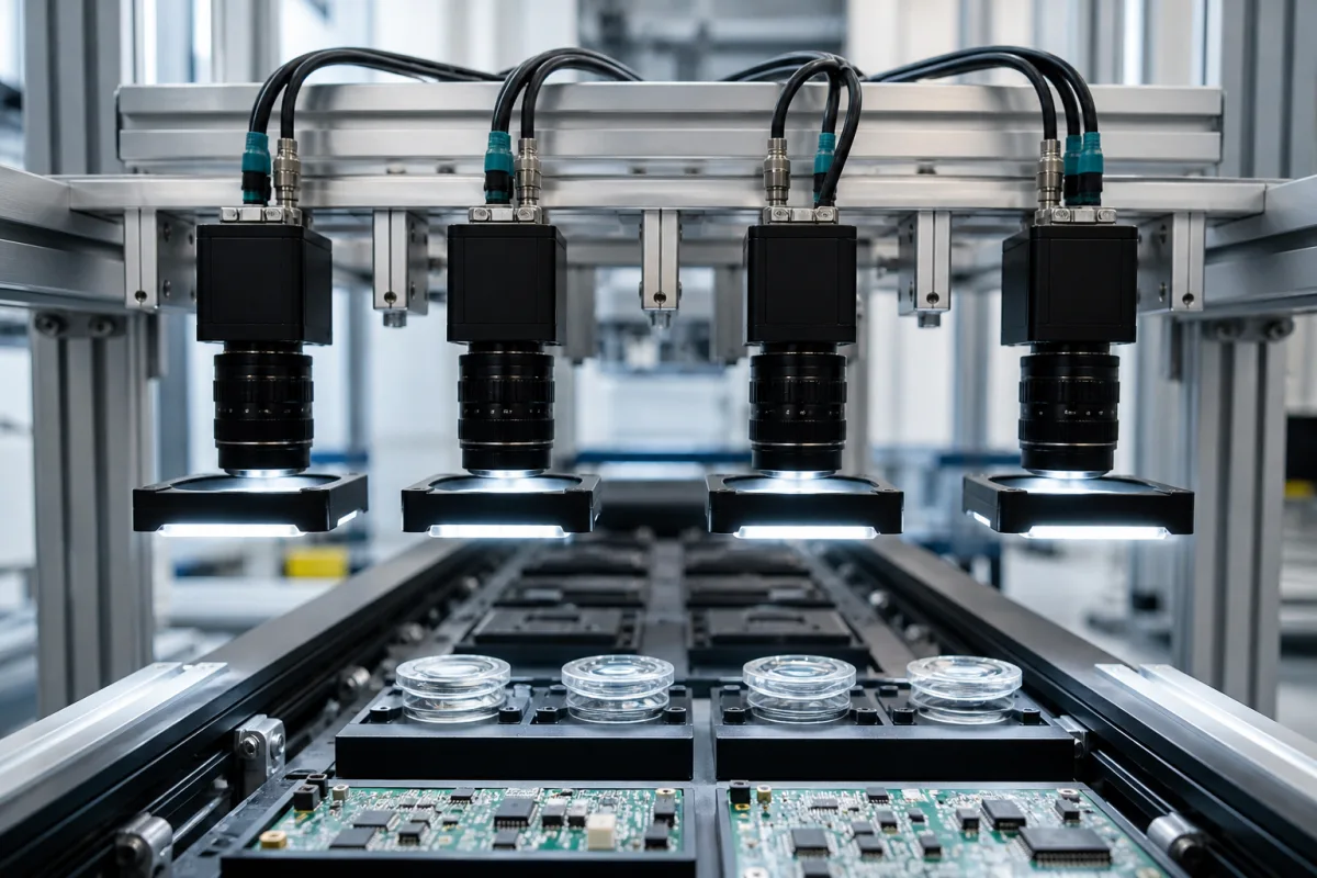
Vision camera array: multiple synchronised GigE cameras on one mount, triggered together with IEEE 1588 PTP and action commands
Multiple GigE cameras on one rail, each with its own lens and light, imaging a row of parts at the same instant · clock synchronisation with IEEE 1588 PTP, scheduled action commands against ordinary broadcast triggers, and the shared 125 MB/s link
Where one camera cannot see everything — a row of parts in a carrier, a wide web, multiple faces of one object — a line uses a camera array: identical cameras fixed side by side on one rail or gantry, each with its own lens and light, imaging its own zone. The images only make sense together if they are taken together. A moving part photographed by camera 1 and camera 4 a few milliseconds apart has moved between frames, and a carrier inspected as one result needs every view from the same cycle. Specifying the array therefore means specifying how the cameras are synchronised and how their data share the network, as well as the cameras themselves.
Arrays of two or more industrial area-scan cameras on a shared mount, imaging adjacent zones or multiple parts at once, and their synchronisation — IEEE 1588 Precision Time Protocol (PTP), GigE Vision action and scheduled action commands, synchronised free run — and shared network bandwidth. Single cameras and resolution sizing are covered on the Machine vision system for inspection and Vision camera module for inline inspection pages; multi-camera casting inspection cells on the Vision system for cast and machined parts page; vision controllers and their camera ports on the Vision processing unit page; PoE interface boards on the Interface board for a vision processing unit page. Line-scan cameras and 3D scanners are outside this page.
CNFX editorial research · Sources checked October 12, 2026 · 5 sources
One clock for every camera: IEEE 1588 PTP and what it achieved on a four-camera rig
Allied Vision's application note explains the principle: a master clock multicasts sync messages, each slave camera calculates the difference between its clock and the master's and keeps adjusting through follow-up and delay messages, and PTP synchronisation is considered achieved while all slaves are within two microseconds of the master. Once clocks agree, future software triggers can be synchronised within two microseconds. [1]
Its test is close to the array pictured here: four cameras at 1 frame per second, one as master and three as slaves, all started with the same acquisition gate time. Over 69 hours of continuous operation the maximum offset between the master's frame timestamp and the slaves' was less than ±1 µs. A second test with two cameras at 15 frames per second, probing each camera's strobe output with an oscilloscope, showed the two about 125 ns apart. [1] Allied Vision adds that a PC-based software master clock on Windows or Linux gave very poor synchronisation with significant jitter, and that it tested a GPS master clock with sub-microsecond timing for real-world time. [1]
Basler's documentation makes the same dependence explicit: the precision of PTP synchronisation depends to a large extent on the network hardware and setup, and for best results it recommends PTP-enabled switches and an external PTP clock with a GPS receiver. With PTP enabled, the tick on its cameras is 1 ns; on older ace models enabling PTP changes the internal tick from 125 MHz (8 ns) to 1 GHz. [2]
Editorial calculation: for a part moving at 1 m/s, a 1 µs offset between cameras corresponds to 1 µm of travel and 125 ns to 0.125 µm, whereas an offset of 5 ms, taken here only for comparison, would correspond to 5 mm.
Editorial note: ask the integrator which camera or device is PTP master, whether the switches are PTP-aware, how synchronisation status is monitored in production, and for timestamp-offset data from the installed array, not only the camera data sheet.
02
Firing all cameras together: broadcast action commands against scheduled ones
GigE Vision cameras can be triggered over the network. Basler's action command sends one broadcast message that makes multiple cameras act at roughly the same time; each camera checks a 32-bit device key, a 32-bit group key and a 32-bit group mask, so sub-groups of the array can be fired separately. For execution at exactly the same time, Basler points to scheduled action commands: the message carries an action time, and every PTP-synchronised camera executes when its timestamp reaches that value. [3][4]
Basler warns that there is an unspecified delay between sending a pylon command and its execution, so the action time should be set from a latched camera timestamp plus a margin; queued scheduled commands execute in ascending order of action time, and commands beyond the queue size are ignored. [4] For synchronous free run, Basler recommends re-running the timer update on all cameras whenever one is disconnected and reconnected, to resynchronise the PTP clocks. [5]
The group mask suits arrays that image in sequence: Basler's example assigns masks so that one command fires cameras 1, 2 and 3 and another fires cameras 3, 4 and 6. [3] Editorial note: on a carrier like the one pictured, the same mechanism lets the line image all four positions at once or only the occupied ones.
Method
How cameras are started
Timing published
Action command (broadcast)
One network message; cameras matching key and group act on receipt
Message carries an action time; each camera acts when its PTP timestamp reaches it
Exactly the same time, given PTP; 1 tick = 1 ns [4]
Synchronous free run
Each camera runs a timer from a shared PTP start time at the same frame rate, or at set offsets
Same time and frame rate, or staggered (example: 100 ms and 200 ms) [5]
Allied Vision acquisition gate time
Triggers held until each camera's timestamp reaches the gate time
Software triggers within 2 µs once clocks are synchronised [1]
03
Four cameras, one link: sharing 125 MB/s
PTP imposes a topology. Allied Vision states that all devices must be on the same network or subnet, connected through a switch to a single port, because no network card could forward PTP sync packets between ports within the two-microsecond requirement; the total bandwidth from all cameras on one GigE connection must then stay under 125 megabytes per second or packets are dropped, and each camera's stream can be limited with its bytes-per-second setting. For full bandwidth from multiple cameras it recommends a switch with a 10 GigE uplink and a 10 GigE network card. [1]
Editorial calculation: four cameras sharing 125 MB/s have about 31 MB/s each; a 5-megapixel monochrome camera at 8 bits per pixel produces 5 MB per frame, so each camera would be limited to about 6 frames per second, and all four together to about 25 full frames per second. With a 10 GigE uplink the shared ceiling rises roughly tenfold. These are illustrative figures for an assumed sensor, before protocol overhead.
04
What to give an integrator for a camera array
Paste it into your enquiry below or into an email to a maker, then replace every bracket.
Parts: [number per cycle; spacing; size; speed of movement]
Cameras: [number; resolution; frame rate; lens and working distance for each]
Synchronisation: [maximum allowed offset between cameras; PTP master; PTP-aware switches; GPS clock if real time is needed]
Triggering: [hardware line, action command, scheduled action command or synchronous free run]
Network: [link speed; switch and uplink; per-camera bandwidth limit]
Mounting: [rail or gantry; camera pitch; adjustment and locking]
Acceptance: [timestamp-offset log from the installed array]
Explore company information and manufacturing capabilities, then discuss the scope of your project with a relevant supplier.
Share this page
Compiled and source-reviewed by the CNFX editorial team.
Each manufacturer above links to the page on that company's own website where the product is listed, with the date we checked it. How we source and review
· Page last updated 13 October 2026
Buyer questions
How closely can GigE cameras in an array be synchronised?
Allied Vision measured four PTP-synchronised cameras within ±1 µs of the master over 69 hours, and two cameras about 125 ns apart on an oscilloscope. [1]
What is the difference between an action command and a scheduled action command?
Basler says an action command makes multiple cameras act at roughly the same time on receipt, while a scheduled action command makes PTP-synchronised cameras act exactly when their timestamps reach a set action time. [3][4]
Can multiple cameras share one GigE link?
Yes, but Allied Vision says their total bandwidth must stay below 125 MB/s or packets are dropped, and recommends a 10 GigE uplink for full bandwidth. [1]
Can a PC act as the PTP master?
Allied Vision found a software master clock on Windows or Linux gave very poor synchronisation with significant jitter. [1]
Sources and what still needs a direct check
Sources checked 2026-10-12. Synchronisation measurements, topology and bandwidth limits come from Allied Vision's PTP application note; PTP set-up, action commands, scheduled action commands and synchronous free run from Basler's camera documentation. Both are camera makers describing their own features.