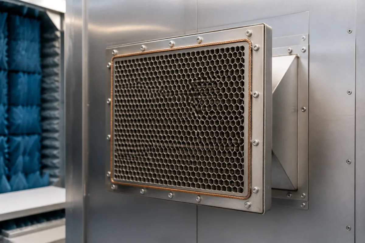
Honeycomb waveguide ventilation panels · Framed honeycomb vents that let air into shielded rooms, enclosures and test chambers while attenuating RF: cell size, honeycomb thickness, single-layer or cross-cell, aluminium, steel or brass, frame and EMC gasket, and measured shielding by frequency
A waveguide ventilation panel is a framed honeycomb grille fitted in the wall of a shielded room, enclosure or EMC test chamber. Each small cell acts as a waveguide below cutoff, so air can pass while radio-frequency energy is strongly attenuated. Ask three things first: what shielding is needed over which frequencies, how much airflow and pressure drop are acceptable, and which material, frame and gasket suit the wall and environment.
Honeycomb waveguide air vents and ventilation panels for shielded rooms, EMC chambers, MRI rooms and electronic enclosures, with their frames and gaskets. EMI filters (see emi filter), shielded doors, absorber panels and shielding enclosures as a whole are outside this page.
CNFX editorial research · Sources checked October 11, 2026 · 4 sources
Holland Shielding offers honeycomb vents for ventilation or for acoustic or visual contact through shielded openings, in cell sizes of 1.6, 3.2, 6.4, 9.5, 12.7 or 19 mm, with 3.2 mm as standard. For high shielding it recommends cross-cell honeycombs built from multiple layers of 6.35, 12.7 or 26 mm thick honeycomb in one frame, and notes that shielding improves as airflow decreases. Slanted honeycomb at 30°, 45° or 60° is offered for rainproof outdoor use. [1]
Its laboratory table for 80 × 80 mm samples with proper gaskets gives, at 100 MHz (E-field), 80 dB for single-layer 6.35 mm honeycomb, 105 dB for cross-cell 6.35 mm, 100 dB for single-layer 12.7 mm and 110 dB for cross-cell 54 mm; at 2 GHz (plane wave) 52, 94, 96 and 98 dB; and at 10 GHz 61, 82, 80 and 90 dB, with results varying in other conditions. [1]
ETS-Lindgren says its waveguide air vents use precision honeycomb in steel or brass, solder-fused for consistent performance, with geometry chosen to balance pressure drop against attenuation from low-frequency magnetic fields to microwave frequencies, for RF-sensitive rooms and MRI suites. [2]
Editorial calculation: 6.35 mm and 12.7 mm are ¼ in and ½ in; with the standard 3.2 mm cell, a 6.35 mm thick layer is about twice as deep as the cell is wide. [1]
A Laird Technologies patent on metallized honeycomb vents explains why cell depth and diameter set the attenuation. Each cell acts as a waveguide that passes wavelengths shorter than its cut-off wavelength and rejects longer ones; the patent's Equation 1 approximates the shielding effectiveness of one cell in dB as a geometry constant K times the depth-to-diameter ratio t/d, times a factor set by the ratio of the interference wavelength to the cut-off wavelength, with K about 32 for circular and 27 for rectangular cells. It gives cell diameters of about 0.06 to 1.0 inch and cell thicknesses of about 0.125 to 1.5 inches, and dielectric honeycomb densities of about 2 to 20 lb/ft³ with wall thicknesses of 0.002 to 0.05 inch. Its test panels were about 0.5 inch thick with about 0.125 inch cells, and showed substantially no difference in airflow from standard aluminium honeycomb. [4]
Editorial calculation: for Holland Shielding's standard 3.2 mm cell in a 12.7 mm thick layer, t/d ≈ 3.97, so K × t/d is about 107 dB with K = 27 and about 127 dB with K = 32 for a single cell well below cut-off. These are geometric estimates; measured panel values, such as the 52–110 dB in Holland Shielding's table, include the frame, gasket and the full cell array, and are what the order should specify. The same patent notes that frames gripping the honeycomb with crimped fingers are limited to about 0.25 inch minimum width and rely on a line contact that twisting can degrade. [4][1]
Give the supplier the shielding required by frequency band and field type, the airflow and allowable pressure drop, opening size and wall construction, material and finish, frame style and fixing, gasket type, indoor or outdoor (rainproof) use, and quantity.
02
Choose material, frame and gasket
Holland Shielding's standard honeycomb material is aluminium, with nickel finish optional; it also offers stainless steel, mild steel or brass, a heavy hot-dip galvanised mild-steel version for military and EMP use, and copper in 6.35 and 12.7 mm thickness. Vents can be framed and pre-drilled or flow-drilled for fasteners, in a range of frame styles, with standard fixing holes of 3.5 mm. [1]
Its framed 9500 series panels are supplied with an aluminium-alloy EMC gasket, or with a knitted wire mesh gasket where galvanic corrosion is a concern, and it says about 95% of the vents it produces are made to customer specification, with some standard sizes in stock. [1]
03
Honeycomb core makers and the shielding data to request
Kunshan Bihore lists 5052 aluminium honeycomb core with EMI shielding ventilation mesh in a range of sizes; ask whether frame, gasket and measured shielding data come with the supply.
Ask any supplier for measured shielding effectiveness by frequency and the test method, cell size and thickness, single or cross-cell build, airflow versus pressure drop, material and finish, frame and gasket details, dimensions, and lead time for custom sizes.
04
Check pressure drop, low-frequency shielding and the wall seal
ETS-Lindgren's waveguide air vent datasheet offers 3.18 mm (1/8 in) and 4.76 mm (3/16 in) honeycomb cells in tin-coated brass or steel, and states pressure drop against face velocity. For the 3/16 in hex cell it lists 0.015, 0.025, 0.035 and 0.050 in of water at 400, 600, 800 and 1000 ft/min; for the finer 1/8 in cell, 0.025, 0.035, 0.045 and 0.060 in of water at the same velocities. [3] For steel honeycomb of either cell size it states 120 dB from 100 kHz to 18 GHz and, for magnetic fields, 25 dB at 1 kHz and 120 dB at 20 kHz; the 1/8 in steel cell adds 100 dB at 40 GHz. Brass honeycomb is rated 25 dB at 1 kHz and 70 dB at 20 kHz for magnetic fields, and a supplemental RF labyrinth is offered for applications above 40 GHz. [3]
The datasheet calls the vent-to-shield seal critical. It recommends soldering or brazing the vent into a lightweight 26 gauge copper or galvanised steel frame; for heavy walls, welded angle-iron frames with the honeycomb-to-frame joint kept below 150°C and skip welding; and, where neither is feasible, Monel or tin-coated gaskets on rigid mating surfaces with fasteners no more than 10.16 cm (4 in) apart. Metal ducts should meet the wall through a dielectric spacing collar so that RF currents on the duct do not reach the shield. [3]
Editorial calculation: taking 1 in of water as about 249 Pa and 1 ft/min as 0.00508 m/s, the 1/8 in cell's 0.060 in of water at 1000 ft/min is about 15 Pa at about 5.1 m/s face velocity, against about 12.5 Pa (0.050 in) for the 3/16 in cell. Ask for the pressure-drop curve at your design airflow and for low-frequency magnetic shielding figures if the room needs them. [3]
The frame and gasket rows decide whether the core's attenuation reaches the wall: ETS-Lindgren calls the vent-to-shield seal critical and specifies soldered or brazed frames, or Monel or tin-coated gaskets with fasteners no more than 4 in apart. [3]
Sets waveguide cut-off and attenuation, approximately K × t/d dB. [4]
Cell size; depth; cell shape.
06
Shielding by frequency, airflow and pressure drop, cell size, thickness, material and frame for a vent order
Shielding, cell size, thickness and material carry Holland Shielding's published ranges and pressure drop ETS-Lindgren's; cutoff frequency, operating temperature, humidity and weight are not stated in the sources and must come from the supplier. [1][3]
Field
What it means and published values
Ask the supplier for
Operating Pressure (MPa)
Pressure drop 0.015–0.060 in of water at 400–1000 ft/min face velocity, by cell size. [3]
1 company lists this product among what they make. Company figures are quoted from each
company's own website; every card states where the relationship came from.
Explore company information and manufacturing capabilities, then discuss the scope of your project with a relevant supplier.
Share this page
Compiled and source-reviewed by the CNFX editorial team.
Each manufacturer above links to the page on that company's own website where the product is listed, with the date we checked it. How we source and review
· Page last updated 13 October 2026
Buyer questions
How much shielding does a honeycomb vent give?
Holland Shielding's lab table gives 52–110 dB from 100 MHz to 10 GHz depending on thickness and layering. [1]
How can vent shielding be increased?
Holland Shielding recommends cross-cell honeycomb built from multiple layers; shielding also rises as airflow decreases. [1]
What materials are honeycomb vents made of?
Aluminium is standard at Holland Shielding; steel, brass and copper are offered, and ETS-Lindgren uses steel or brass. [1][2]
How much pressure drop does a honeycomb waveguide vent add?
ETS-Lindgren's datasheet lists 0.015 to 0.050 in of water for its 3/16 in hex cell and 0.025 to 0.060 in of water for its 1/8 in cell, across face velocities of 400 to 1000 ft/min. [3]
Why does a deeper honeycomb vent shield better?
Each cell is a waveguide below cut-off; a Laird patent approximates attenuation as K × t/d dB (K about 32 for circular, 27 for rectangular cells), so attenuation rises with depth relative to cell diameter. [4]
Sources and what still needs a direct check
Sources checked 2026-10-11. Holland Shielding Systems and ETS-Lindgren make honeycomb waveguide vents; a Laird Technologies patent sets out the cell geometry behind vent attenuation.