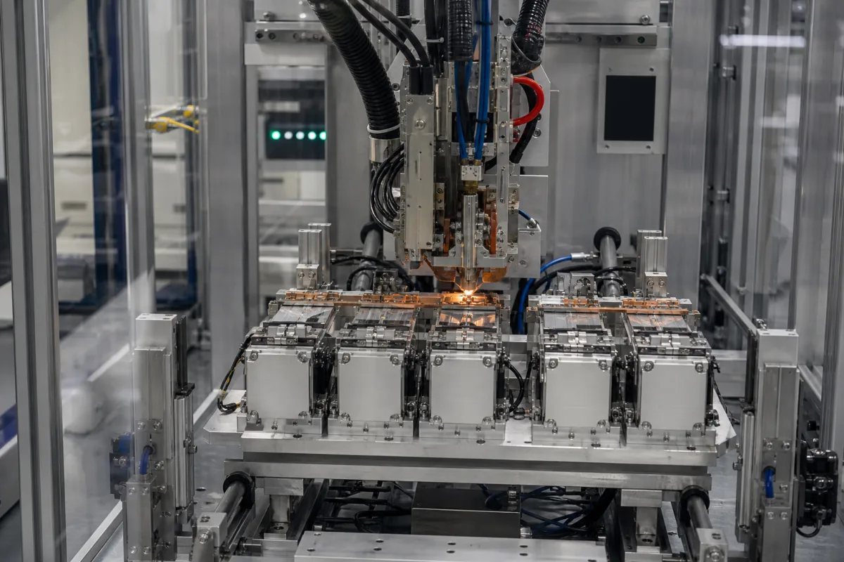
Battery busbar welding station (cell-to-busbar laser welding in module and pack lines)
Battery assembly line station · Cell-to-busbar fit-up and clamping, laser source and weld monitoring, cycle time per cell
A battery busbar welding station is the line station in a battery module or pack assembly line that clamps the busbars onto the cell terminals and welds each connection, then checks the welds before the module moves on. Ask three things first: how the station brings every busbar into contact with its terminal, which laser source, optics and process window it uses for your busbar material and thickness, and how each weld is monitored and reworked inside the cycle.
Automated welding stations for joining busbars or cell connectors to the terminals of cylindrical, prismatic or pouch cells in battery module and pack assembly lines, with their clamping, vision and weld-monitoring equipment. General-purpose fiber laser welding machines — handheld welders, CNC and gantry welders and laser welding robots — are covered on the Laser welding machine page; ultrasonic tab welders, cell manufacturing equipment and battery testers are outside this page.
CNFX editorial research · Sources checked October 12, 2026 · 3 sources
Control the busbar-to-terminal fit-up and clamping
A Sanyo Electric patent on busbar welding explains why fit-up drives this station: when a gap opens between the busbar and the electrode terminals to be laser-welded, reliable and stable welding cannot be carried out, and in a battery system with a plurality of cells such gaps are very difficult to eliminate because of dimensional error in the cells and the busbar. [2]
The patented design guides each terminal's protruding portion into a cut-away in the busbar and leaves an exposure gap — preferably more than 1 mm, more preferably 2 mm or more — so that the inner edge is fillet-welded to the terminal face. It gives the welding width as, for example, 0.8 mm or more (preferably 1 mm or more, further preferably 1.2 mm or more) and 5 mm or less, and the welding-plate thickness as, for example, 0.3 mm or more and 2 mm or less, preferably up to 1.6 mm. [2]
Laserax's battery pack laser welding machine clamps each cell-to-busbar connection with 4 to 8 SCARA robots while the laser welds in parallel; the clamping tools give pressure feedback and motorised angle adjustment, and the clamping position is corrected from 3D-vision feedback. Laserax lists a typical weld-to-cell accuracy of ±100 µm with vision. [1]
Give the supplier the cell format and terminal geometry, busbar material, thickness and coating, the joint design (lap, fillet, through-hole), cell count and layout per module or pack, the cell-height and position tolerances you can hold, the line cycle time, how parts arrive (conveyor, AGV, pallet), and the weld acceptance tests you will run.
02
Size the laser source, optics and in-cycle weld monitoring
Laserax's product sheet lists a 2000 W single-mode continuous-wave ytterbium fiber laser at 1070 nm, described as typical for busbars under 2 mm, with 1000–6000 W single-mode, multi-mode and ring-core sources available. It welds nickel-plated steel, aluminium, copper and stainless steel; scanning-optics and 3D-vision fields of view are 400 × 400 mm or 650 × 650 mm, and typical welding speeds are 100 ms per cell (2 welds, 21xxx series), 150 ms per cell (46xx series) and 300 ms per prismatic pole. [1]
The same sheet states a typical power consumption of 27 kW with a 2000 W source and 40 kW with a 6000 W source, an operating range of 15–35 °C at under 70% humidity, and weld monitoring that analyses photodiode emissions and HD images to identify the defect type and trigger rework in the same station and cycle. [1] Editorial calculation: at the typical 100 ms per cylindrical cell, 1,000 cells take 1,000 × 0.1 s = 100 s of welding time, before clamping moves, part transfer and rework are added. [1]
Choi and co-authors' open-access review of tab-to-busbar welding in EV packs describes a laser welding set-up as a laser device, a welding head and a clamping fixture with shielding gas, and reports work on copper with multi-mode fiber lasers at 3–8 kW in which raising power beyond 4 kW altered the process limit, and helium shielding gave on average about 15% lower penetration depth and about 25% larger bead width than welding without shielding gas. [3] The review calls for closed-loop in-process control that compensates for variation in surface quality and gap fit-up. [3]
03
Parts of a cell-to-busbar laser welding station
Part
Role
Fix in the order
Laser source
Single-mode, multi-mode or ring-core fiber laser; 1000–6000 W listed by Laserax. [1]
Laser safety enclosure, fume and dust extraction. [1]
Safety class and extraction.
04
Values to fix before quoting a busbar welding station
Current, voltage and electrode force in this list apply when the station uses resistance welding; for laser stations ask for laser power, clamp pressure and monitoring instead.
Field
What it means and published values
Ask the supplier for
Welding current (kA)
Resistance-welding stations only.
Range and control mode.
Welding voltage (V)
Resistance-welding stations only.
Range.
Welding time (ms)
Laserax typical: 100 ms per cell (2 welds, 21xxx). [1]
Time per joint on your cells.
Electrode force (kN)
Resistance welding; laser stations use clamp pressure with feedback. [1]
Force range and monitoring.
Positioning accuracy (mm)
Laserax typical: ±100 µm (±0.1 mm) with vision. [1]
Explore company information and manufacturing capabilities, then discuss the scope of your project with a relevant supplier.
Share this page
Compiled and source-reviewed by the CNFX editorial team.
Each manufacturer above links to the page on that company's own website where the product is listed, with the date we checked it. How we source and review
· Page last updated 13 October 2026
Buyer questions
Why does a busbar welding station need clamping?
A Sanyo patent notes that a gap between busbar and terminal prevents reliable laser welding, and that dimensional error in cells and busbars makes such gaps hard to eliminate. [2]
How fast does a busbar laser welding station weld?
Laserax lists typical times of 100 ms per cylindrical cell (2 welds, 21xxx) and 300 ms per prismatic pole. [1]
What laser power is used for busbar welding?
Laserax lists 2000 W single-mode as typical for busbars under 2 mm, with 1000–6000 W available; the Choi review reports copper studies at 3–8 kW. [1][3]
Sources and what still needs a direct check
Sources checked 2026-10-12. Laserax is a laser equipment maker describing its battery pack welding machine; the Sanyo Electric patent describes a busbar-to-terminal joint designed for laser welding; the Micromachines review by Choi and co-authors surveys tab-to-busbar welding methods.