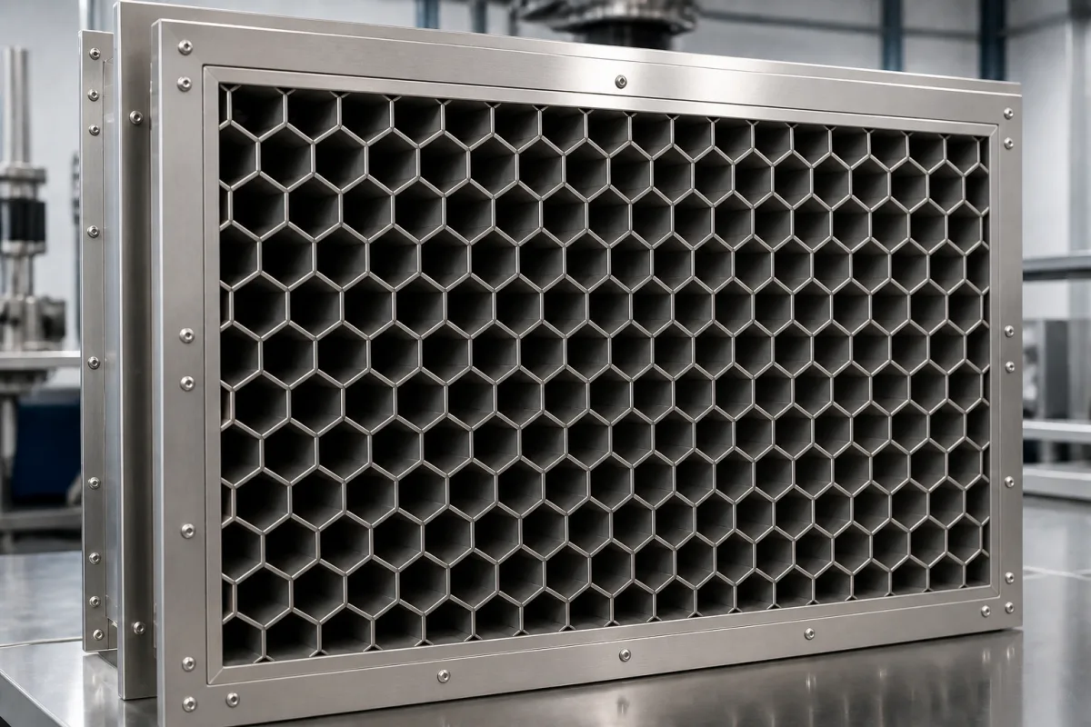
Waveguide-below-cutoff ventilation array for EMP protection: large 50 mm cells, 140–210 mm deep
Large-cell waveguide-below-cutoff arrays for EMP-protected ventilation · cell width, cell depth and the airflow they cost
An air duct through an electromagnetic-pulse (EMP) hardened wall is an opening the pulse can couple through. A waveguide-below-cutoff array closes it electrically while leaving it open to air: the opening is divided into an array of metal tubes, each too narrow for the frequencies of concern to propagate, so the fields decay along the tube's depth. For EMP work the cells are wide and deep, sized for the 10 kHz to 1 GHz band, and the design question is how deep they must be and how much airflow that costs.
Waveguide-below-cutoff ventilation arrays with large cells (tens of millimetres) and deep tubes, built into the air penetrations of EMP-protected facilities, ships and shelters and assessed against MIL-STD-188-125 shielding requirements. Fine-cell honeycomb vent panels for shielded rooms, EMC chambers, MRI rooms and enclosures are covered on the Waveguide ventilation panel page; antennas, including slotted waveguide array antennas, are covered on the Antenna system for wireless communication page.
CNFX editorial research · Sources checked October 12, 2026 · 3 sources
Depth: 140–210 mm cells passed 80 dB where a five-diagonal rule would ask for about 350 mm
Cheng, Tsai and Hwang (IEEE Access, 2026) built full-scale 20 × 30 waveguide-below-cutoff ventilation arrays with 50 × 50 mm square apertures in an AA5083 aluminium alloy enclosure and measured them to MIL-STD-188-125 from 10 kHz to 1 GHz with loop, biconical and log-periodic antennas. [1] Their paper states that MIL-STD-188-125 traditionally recommends a waveguide depth of more than five times the aperture diagonal. [1]
The authors conclude that, for the configuration they tested, the depth can come down from about 350 mm (5 × the 70 mm diagonal) to 140–210 mm, a reduction of about 40–60%, and they observed stronger attenuation at higher frequencies. [1] They also cite earlier experiments showing that seams or gaps in ship hulls can cut shielding effectiveness by 15–30 dB, so the frame-to-bulkhead joint matters as much as the cells. [1]
Editorial calculation: a 50 mm square cell has a diagonal of 50 × √2 ≈ 70.7 mm; five diagonals is about 354 mm, and 140, 175 and 210 mm are 1.98, 2.47 and 2.97 diagonals.
The reduced depth is the authors' result for 50 mm square cells in a 20 × 30 array; ask the supplier for measured shielding effectiveness of the actual array and frame against the project's requirement.
02
Cell width sets the cut-off: 50 mm cells near 3 GHz, 15 mm near 10 GHz
For a rectangular tube of width a, the dominant TE10 mode has a cut-off frequency fc = v / 2a, and below cut-off the field decays as e^(−αz); the IEEE Access paper approximates a single tube's shielding effectiveness as SE ≈ 8.686 α d, so it grows roughly linearly with depth d. [1] A Siemens patent on ventilation insets for shielded cabins describes honeycomb insets as a multiplicity of waveguides side by side that attenuate below their cut-off frequency, and gives examples: welded, roughly rectangular sections for about 1 GHz, hexagonal or square cells for about 10 GHz and soldered capillary tubes for 35 GHz. [3]
Editorial calculation with the paper's single-tube formula, taking free-space wave speed: far below the 3 GHz cut-off of a 50 mm cell α approaches π / a ≈ 62.8 Np/m, giving about 76, 96 and 115 dB for 140, 175 and 210 mm depth; at 1 GHz α ≈ 59.2 Np/m, giving about 72, 90 and 108 dB. These single-tube estimates are not the array's measured values, which exceeded 80 dB in every case. [1]
Cut-off frequency
Example from the sources
Editorial calculation: square-cell width a = c / 2fc
Grid, honeycomb or multi-ply arrays: what 80–100 dB costs in air pressure
Pang, Ahn and Yook (Korean Society for Geothermal and Hydrothermal Energy journal, 2016) compared waveguide-below-cutoff arrays for EMP shielding by computational fluid dynamics: grid, honeycomb and multi-layer arrays of 2, 4, 6 and 8 plies. [2]
With 1 mm thick waveguide walls and a 30 mm module, the grid and honeycomb arrays reached the highest centre-line velocity, 17.5 m/s, about 2.5 m/s faster than at the inlet; at shielding effectiveness of 80 and 100 dB the grid array had the lowest average pressure drop and the 8-ply array the highest. [2] With 0.1 mm thick walls and 100 dB, the pressure drop of the 6-ply multi-layer array did not rise markedly with inlet velocity compared with the other types. [2]
State the airflow and allowed pressure drop of the ventilation system together with the shielding requirement; the array type, wall thickness and depth are then chosen to meet both.
04
Data for an EMP ventilation array enquiry
Paste it into your enquiry below or into an email to a maker, then replace every bracket.
Requirement: [standard; shielding effectiveness in dB; frequency range]
Opening: [duct size; wall or bulkhead type; space available for depth]
Array: [cell shape and width; depth; wall thickness; material]
Air: [airflow; face velocity; allowed pressure drop]
Installation: [frame and bonding to the wall; gasket or weld; test method and acceptance test]
Explore company information and manufacturing capabilities, then discuss the scope of your project with a relevant supplier.
Share this page
Compiled and source-reviewed by the CNFX editorial team.
Each manufacturer above links to the page on that company's own website where the product is listed, with the date we checked it. How we source and review
· Page last updated 13 October 2026
Buyer questions
How deep must waveguide-below-cutoff ventilation cells be for EMP protection?
The IEEE Access study cites MIL-STD-188-125 as traditionally recommending more than five aperture diagonals, but measured over 80 dB from 10 kHz to 1 GHz with 50 mm cells only two to three diagonals (140–210 mm) deep. [1]
What sets the cut-off frequency of a cell?
Its width: for a rectangular tube the dominant mode cuts off at fc = v / 2a, so a 50 mm cell cuts off at about 3 GHz (editorial calculation). [1]
Which array type costs the least air pressure?
In Pang, Ahn and Yook's CFD study the grid array had the lowest average pressure drop and the 8-ply multi-layer array the highest. [2]
Do honeycomb insets work the same way?
Yes. A Siemens patent describes them as a multiplicity of waveguides side by side attenuating below cut-off, with examples for about 1, 10 and 35 GHz. [3]
Sources and what still needs a direct check
Sources checked 2026-10-12. Array geometry, test method and measured results come from Cheng, Tsai and Hwang's IEEE Access paper; airflow comparisons from Pang, Ahn and Yook's KSGEE paper; cut-off examples from Siemens' patent US4550545A. Values apply to the arrays described.