Editorial Technical Reference

Welding Head

This page explains how Welding Head is classified within Machinery and Equipment Manufacturing. Technical values and manufacturer relationships are research references; confirm the current specification and supplier evidence for each order.

Technical Definition & Core Assembly

The component of an electric motor rotor lamination stacking and welding machine that performs the actual welding operation on rotor laminations.

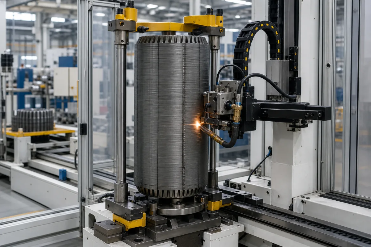
Representative product image. Confirm appearance and specifications with the manufacturer.

Product Specifications

Technical details and manufacturing context for Welding Head

Definition
A welding head is a critical component of electric motor rotor lamination stacking and welding machines. It is the end-effector that applies precise welding energy (typically resistance or laser) to fuse individual steel laminations together, forming a rigid rotor core. It operates under automated control to ensure consistent weld quality, penetration, and positioning across the rotor stack. The welding head is designed for integration into automated production lines, where it interfaces with the machine's control system and power source. It is available in configurations that support resistance welding or laser welding, depending on the application requirements. The head includes a structural frame, electrodes or a laser focusing lens, and provisions for cooling and electrical or optical connections. The materials used in its construction include copper alloy for electrodes, high-strength steel for the structural frame, and ceramic insulation for electrical isolation. The welding head is characterized by parameters such as rated power (5–15 kW), welding current (100–500 A), welding speed (0.5–2.0 m/min), positioning accuracy (±0.05 mm), repeatability (±0.02 mm), supply voltage (380–480 V AC, three-phase, 50/60 Hz, per IEC 60038), operating temperature (5–40 °C), ingress protection (IP54–IP65 per IEC 60529), weight (50–120 kg), and cooling method (water-cooled). These values are reference ranges and must be verified for the specific model and application. The welding head is a component, not a standalone machine, and its performance depends on the overall system. When selecting a welding head, consider the lamination material and thickness, required weld quality, production speed, and integration with existing equipment. Verify model-specific specifications and standards with the legal manufacturer or supplier. Regular maintenance includes checking electrode wear, cooling system integrity, and alignment. Failure to maintain proper cooling or electrode condition can lead to inconsistent welds or equipment damage. The welding head is not intended for manual operation; it is designed for automated use within a machine.
Working Principle
The welding head receives electrical energy or laser beam energy from the machine's power source. It positions electrodes or a laser focusing lens against the rotor lamination stack at pre-programmed points. Upon actuation, it applies concentrated heat (via electrical resistance or laser absorption) to melt and fuse the thin steel laminations together. It then retracts, allowing the weld to solidify and create a permanent bond between layers.
Common Materials
Copper alloy (for electrodes), High-strength steel (for structural frame), Ceramic insulation
Technical Parameters
ParameterTypical rangeNotes & selection driver
Rated Power5–15 kWDetermines welding speed and penetration depth.
Welding Current100–500 AAdjustable for different lamination thicknesses.
Welding Speed0.5–2.0 m/minAffects heat input and distortion.
Positioning Accuracy±0.05 mmEnsures consistent weld seam placement.
Repeatability±0.02 mmCritical for high-volume production.
Supply Voltage380–480 V ACThree-phase, 50/60 Hz.IEC 60038
Operating Temperature5–40 °COutside this range, cooling may be required.
Ingress ProtectionIP54–IP65Protects against dust and water jets.IEC 60529
Weight50–120 kgAffects mounting and handling.
Cooling MethodWater-cooledRequired for continuous high-current operation.

Ranges are indicative industry figures for RFQ preparation, not a supplier commitment. Confirm every value and standard with the legal manufacturer before ordering.

Components / BOM
  • Electrode Holder
    Secures and aligns the welding electrodes, providing electrical contact and mechanical stability.
    Material: Copper alloy
  • Force Actuator
    Applies and controls the precise downward force of the welding head onto the rotor stack.
    Material: Steel with pneumatic/hydraulic components
  • Cooling Jacket
    Circulates coolant to prevent overheating of the welding head during operation.
    Material: Stainless steel or copper
  • Welding Electrodes
    The consumable tips that carry the current into the lamination stack and melt it.
  • Laser Focusing Lens Optional
    Focuses the beam onto the stack on laser-welding versions.

Applied To / Applications

This component is essential for the following industrial systems and equipment:

Industrial Ecosystem & Supply Chain Structure

Complementary Systems
Downstream Applications
Specialized Tooling

Application Fit & Sizing Matrix

Operational Limits
pressure: 0.5 to 3.0 bar (electrode contact force)
other spec: Welding current: 5-20 kA DC, Cycle time: 0.5-3.0 seconds per weld
temperature: Ambient to 150°C (welding zone localized heating)
Media Compatibility
✓ Electrical steel laminations (silicon steel) ✓ Copper welding electrodes ✓ Inert gas shielding (argon/CO2 mix)
Unsuitable: Corrosive/acidic environments (causes electrode degradation)
Sizing Data Required
  • Rotor lamination stack diameter (mm)
  • Required weld count per stack
  • Production rate (stacks per hour)

Reliability & Engineering Risk Analysis

Failure Mode & Root Cause
Electrode tip degradation
Cause: Excessive heat buildup from improper welding parameters (current, pressure, time) leading to pitting, mushrooming, and material transfer
Misalignment or mechanical wear in the head assembly
Cause: Lack of regular calibration, worn bearings/bushings, or impact damage causing inconsistent weld quality and premature component failure
Maintenance Indicators
  • Irregular or sputtering arc sound during operation, indicating poor electrical contact or contaminated electrodes
  • Visible sparking outside the weld zone or excessive spatter, suggesting misalignment or incorrect pressure settings
Engineering Tips
  • Implement a strict electrode dressing and replacement schedule based on weld count, using proper tip dressing tools to maintain optimal geometry and conductivity
  • Establish routine alignment checks and force calibration using certified gauges, ensuring consistent pressure and perpendicularity to the workpiece

Indicative industry ranges for design and RFQ preparation. Confirm the exact figures and applicable standard with the manufacturer before specifying.

Compliance & Manufacturing Standards

Applicable Standards
ISO 15614-1:2017 (Specification and qualification of welding procedures) ANSI/AWS D1.1/D1.1M:2020 (Structural Welding Code - Steel) EN ISO 3834-2:2021 (Quality requirements for fusion welding of metallic materials)

Quoted from the published standard.

Manufacturing Precision
  • Bore alignment: +/-0.05mm
  • Surface flatness: 0.08mm per 100mm length
Quality Inspection
  • Visual Inspection per ISO 17637
  • Hardness Testing per ISO 9015-1

Manufacturers of Welding Head

1 company lists this product among what they make. Company figures are quoted from each company's own website; every card states where the relationship came from.

Scanner Optics Co., Ltd.
Shenzhen, Guangdong, CN
Listed on the company's own website · profile compiled by CNFX from public sources

Manufacturer listings support early research and capability understanding. They are not certification, ranking, or transaction guarantees.

Technical documentation
Request current drawings, revision history, and a signed specification sheet.
Manufacturing capability
Verify equipment lists, process limits, capacity, and representative production evidence.
Inspection readiness
Confirm test methods, calibrated equipment, sampling plans, and traceable reports.
Supplier transparency
Check the legal entity, factory address, ownership, certifications, and direct contacts.

CNFX does not score or rank suppliers. Buyers must verify all claims and documents with the legal manufacturer before ordering.

Supply Chain Compatible Machinery & Devices

Heavy-Duty CNC Plasma Cutting Machine

The Heavy-Duty CNC Plasma Cutting Machine is a standalone industrial device designed for cutting conductive metals such as steel, stainless steel, aluminum, and copper alloys.

Explore Specs →
Automated Powder Coating System

Integrated industrial system for applying dry powder coatings to metal substrates.

Explore Specs →
Centrifugal Pump Impeller

The centrifugal pump impeller is a critical rotating component that converts mechanical energy from the motor into kinetic energy in fluid systems.

Explore Specs →
High-Precision CNC Laser Cutting Machine

Computer-controlled industrial machine using focused laser beams to cut sheet metal with micron-level accuracy.

Explore Specs →

Frequently Asked Questions

What is the function of a welding head in a rotor lamination stacking and welding machine?

The welding head is the end-effector that applies welding energy (resistance or laser) to fuse steel laminations together, forming a rigid rotor core. It operates under automated control to ensure consistent weld quality and positioning.

What are the typical power and current ranges for this welding head?

The rated power is typically 5–15 kW, and the welding current is 100–500 A. These are reference ranges; actual values depend on the specific model and application. Always verify with the manufacturer.

What cooling method is used, and why is it important?

The welding head is water-cooled. This is required for continuous high-current operation to prevent overheating and maintain consistent weld quality. Ensure the cooling system is properly maintained.

What standards apply to this welding head?

The supply voltage reference is per IEC 60038, and ingress protection is per IEC 60529. These standards are procurement references; they do not guarantee certification. Verify compliance with the supplier.

Data Basis

Editorial classification, named public sources where available, and source-reviewed manufacturer records.

Preliminary Technical Classification
This page supports structured research, RFQ preparation, and supplier evaluation. It does not replace buyer-led supplier qualification, standards review, or technical approval.
Buyer enquiry

Request manufacturing insight for Welding Head

Ask for use case, specification boundaries, supplier type, and RFQ preparation information for this product.

Where it goes
Straight to the CNFX editorial desk, and to the manufacturer if this product is linked to a claimed profile. Nothing is broadcast to a supplier list.
Your details stay here
We do not sell or rent enquiry data, and we do not add you to a mailing list. Used only to answer this request.
No commission, no middleman
CNFX is a directory. We take no cut of any order and never negotiate on a supplier's behalf.
What we don't claim
A listing is not an endorsement. Qualify every supplier and verify every figure yourself before ordering.

Your business information is used only to process this request.

Thank you! Your message has been sent. We'll respond within 1–3 business days.
Sorry, we couldn't send your message. Please try again, or email us at contact@cnfx.com.

Need to Manufacture Welding Head?

Compare manufacturer profiles with relevant product and process capability.

Previous Product
Z-axis Ram/Spindle
Last Product
Get QuotesChat