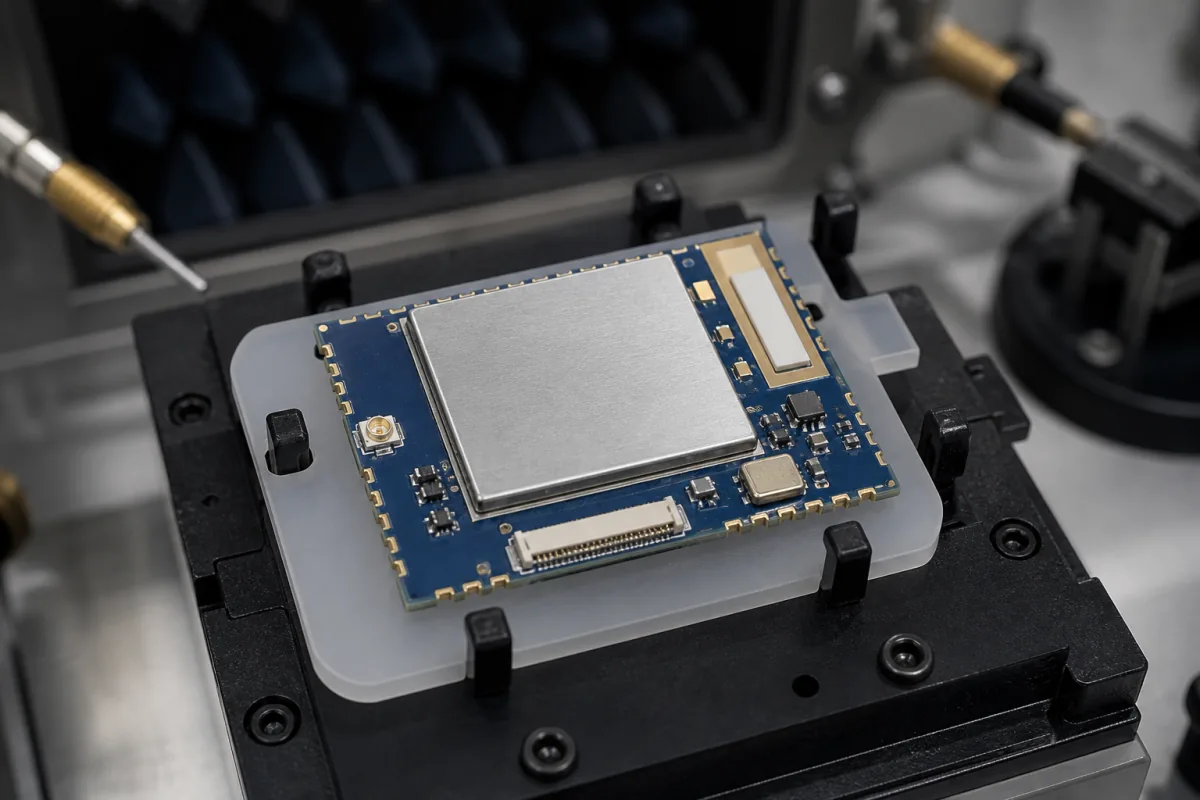
Every module that leaves a line has to prove its radio works, in seconds and without a network. The module in the illustration sits on a fixture inside an absorber-lined enclosure with RF probes alongside: that is the production test step this page covers, from the firmware that puts the radio in a test mode to the offsets that keep one test station reading the same as the next.
Covers end-of-line RF and functional testing of solder-down radio modules and products built on them: RF test firmware and serial command control, tester and reference-board schemes, shielded enclosures, pogo-pin module fixtures, conducted and coupled measurement, frequency-offset calibration, transmit-power and receive packet-error checks, and test-station path-loss calibration. Choosing and certifying a module is on Wireless module (embedded radio module); Wi-Fi band and MIMO selection is on Wi-Fi module (802.11 WLAN); enclosed link radios are on Wireless transceiver; nRF24L01+ class parts are on 2.4 GHz SPI transceiver module; cellular DTUs are on Cellular modem.
CNFX editorial research · Sources checked October 12, 2026 · 4 sources
Espressif's production testing guide describes two ways to test the radio of modules and boards built on its Wi-Fi chips.
Both schemes must run inside a shielded enclosure. The module is brought up through six test points (3.3 V, GND, RXD, TXD, EN and GPIO0), with GPIO0 held low for download mode, the main mode used in production, and high for flash-run mode when reading logs.
The Sigfox production guide takes the same approach for its devices: no network registration, no special Sigfox equipment, and AT commands or library test calls to drive continuous-wave, modulated transmit and receive modes, with a whole device test under 15 seconds.
Scheme
How it works
What the guide says about it
RF general-purpose tester
RF_Test_FW.bin is loaded into chip RAM; a PC tool sends serial commands that put the module into set transmit and receive modes; the RF tester measures each mode
Called the general industry standard; the tester maker's mass-production tool has to support the chip, or the customer adapts it through the tester's interfaces
Signal board (ESP-BAT32 for ESP32 series)
A reference board talks to the module under test and judges the exchanged data
Espressif's own standard; low hardware cost and easy setup; only one signal board per area of radio coverage, otherwise boards interfere, so more than one board needs a shielded room or shield boxes
Ask the module supplier which test firmware and command set ships with the module, whether it supports your tester's mass-production software, and how the test firmware is replaced by application firmware afterwards.
02
Pogo fixture and shield box
Espressif's test fixture instruction sets out how a module fixture is built so that fixtures do not become the source of test failures.
A module fixture has a mounting panel that holds the module, a handle, and a bottom box containing serial-port boards linked to the PC over USB. Pressing the handle brings metal probes under the panel into contact with every module pin and powers it up; lifting it must separate all probes and cut power. The gap between the moving plate and the panel must let the probes reach all pins without crushing the module or its shield can.
The antenna area must be fully exposed. The mounting panel must not be metal, and metal parts near the antenna should be kept to a minimum. Espressif's fixtures are built one-to-several, with one-to-four given as its example set-up: four modules per handle press and four serial-port boards screwed into the box. With more than one serial port on one USB hub, the hub needs its own supply.
For a module with an antenna connector, Sigfox says module tests should be conducted only, through the connector, testing transmit and receive separately if they use different paths, with a Faraday cage as an option. For an end product with no connector access, it adds a coupler with a calibrated radiated loss.
Situation (Sigfox guide)
Test method
Module manufacturing
Conducted tests only; both paths if TX and RX differ; optional Faraday cage
End product, antenna connector accessible
Conducted tests
End product, no connector access
Coupler with calibrated radiated loss
The illustrated module carries a U.FL-type connector and a chip antenna, so it can be tested either way; state on the drawing which path the production test uses.
03
What the RF checks measure
Sigfox's production guide gives short, fixed procedures that show what a pass/fail radio test needs to catch.
The 22 dBm and 14 dBm levels differ by 8 dB, a factor of about 6.3 in power (Editorial calculation), so a wrong radio configuration shows up at once.
Throughput: at the 15-second upper bound Sigfox quotes, one fixture position completes 240 tests an hour, and a one-to-four fixture running all positions together 960, before loading time (Editorial calculation combining figures from two different suppliers' guides).
Check
Procedure in the Sigfox guide
What it catches
Carrier frequency calibration
Continuous wave at the set frequency; read it on a spectrum analyser; store the offset in non-volatile memory; re-read: offset must be 0
Carrier off its set frequency
Transmit power
Five pseudo-random BPSK frames back to back; read on a spectrum analyser or power meter; expect 14 dBm or 22 dBm depending on radio configuration
Faults between RF chip and RF output
Receive sensitivity / PER
Device in receive for 30 s; generator sends 10 GFSK frames at −120 dBm; count frames received
Loss in the receive path
RSSI calibration
Generator sends frames at sensitivity +10 dB, device reports RSSI, offset = reported − sent level is stored in non-volatile memory; repeat at sensitivity +30 dB to check
Uncalibrated signal-strength reporting
Ask for the pass limits on frequency offset, transmit power and packet error rate at each channel tested, and how many channels are sampled per module.
04
Path-loss calibration across test stations
Apple's patent US 8,903,672 B2 sets out why parallel test stations disagree unless each is calibrated as a whole.
In the set-up the patent describes, the device under test is connected to the instrument through an RF cable with its own loss, and each station's chain of instrument, cable and fixture has a unique loss characteristic. Measuring cables with a vector network analyser misses the fixture loss and differences between instruments, so one station's readings end up offset against another's.
The patent calibrates each station end to end. For uplink, a signal generator at known power feeds the station's fixture and the station's tester measures it; the difference gives an uplink error per frequency. For downlink, a calibrated plate and power meter sit on the fixture and measure what the tester sends at a requested level. The errors go into a station error table, and computing equipment loads the offsets into each station so that results line up.
Direction
Source
Measured by
Offset
Uplink
Signal generator at known level into fixture
Station test unit
Known level − measured level, per frequency
Downlink
Station test unit at requested level
Calibration plate + power meter
Requested − measured − plate path loss, per frequency
Ask how often each station's offsets are re-measured, whether a reference module is kept for daily checks, and how probe and cable wear is tracked.
05
What to agree with a module supplier about production test
Paste it into your enquiry below or into an email to a maker, then replace every bracket.
Name the radio, bands and channels to test, conducted or coupled measurement, and the fixture count per handle. Ask for the test firmware and command set, the tester or signal-board scheme used, the shield-box isolation, the pass limits for frequency offset, transmit power and receive packet errors, the station calibration method and interval, and whether per-module results and stored calibration values are logged against serial number.
Listed suppliers for wireless communication modules
2 companies list this product among what they make. Company figures are quoted from each
company's own website; every card states where the relationship came from.
NiceRF Wireless
TBC
NiceRF's site lists LoRa and LoRaWAN SPI modules (SX1262, SX1276, LLCC68 and others), transparent wireless UART modules, 2.4 GHz modules and a certified-modules range with FCC, CE-RED and IC entries.
Reallin's site lists a Wireless Communication Modules range alongside its energy meters, data concentrators and LoRa gateways, naming Bluetooth, Wi-Fi, LoRa, LTE and NB-IoT technologies.
Explore company information and manufacturing capabilities, then discuss the scope of your project with a relevant supplier.
Share this page
Compiled and source-reviewed by the CNFX editorial team.
Each manufacturer above links to the page on that company's own website where the product is listed, with the date we checked it. How we source and review
· Page last updated 13 October 2026
Buyer questions
Does a radio module need a network to be tested in production?
No. Espressif loads RF test firmware and drives transmit and receive modes over serial commands, and Sigfox's guide tests devices without registering them on its network, in under 15 seconds. [1][3]
Why must the test run in a shield box?
Espressif requires a shielded enclosure for both its schemes, and warns that more than one signal board in the same coverage area interferes unless they sit in a shielded room or boxes. [1]
Can the fixture be metal?
Espressif's fixture instruction says the mounting panel must not be metal, metal near the antenna should be minimal, and the antenna area must be fully exposed. [2]
Why do two test stations give different power readings for the same module?
Each station's instrument, cable and fixture has its own loss. Apple's patent calibrates each station end to end per frequency and loads the offsets so that stations agree. [4]
Sources and what still needs a direct check
Sources checked 2026-10-12. A chip maker's production test guide and fixture instruction, a network operator's device production test guide, and a patent on test-station calibration.