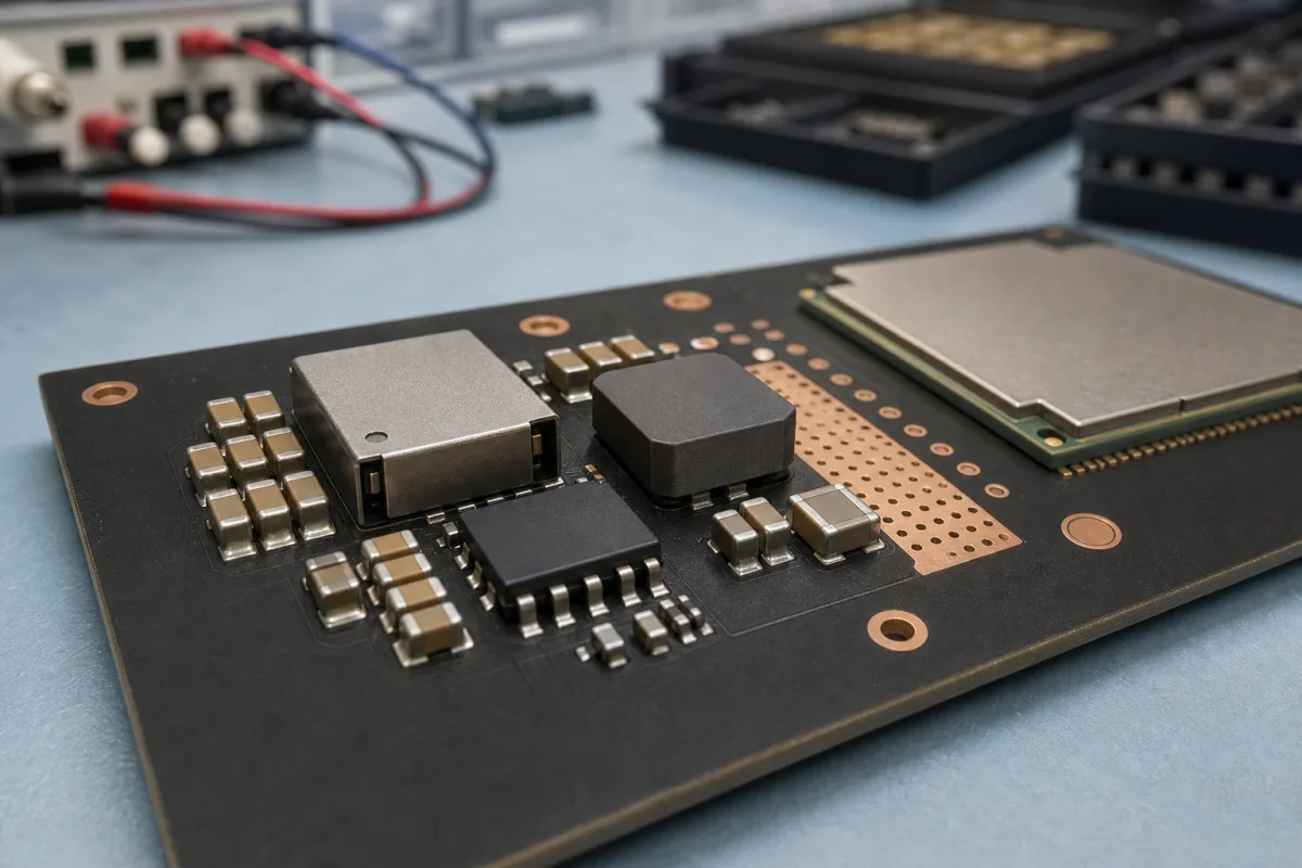
Power regulator for a Wi-Fi module supply rail (the 3.3 V regulator and capacitors that keep the radio running while it transmits)
Feeding a Wi-Fi module from a single 3.3 V rail · at least 500 mA, transmit current steps that can collapse the rail, 10 μF at the entrance and at the RF supply pin, and a low-noise buck with bypass mode for Wi-Fi power amplifiers
A Wi-Fi module draws little current while idle and a sharp step of current each time it transmits. The regulator ahead of it, whether a linear LDO or a switching buck, has to hold the rail inside the chip's operating window through those steps. The chip vendor's schematic checklist gives the voltage, current and capacitance to design to; the choice between linear and switching then depends on input voltage, heat and RF noise.
The regulator and supply-rail parts that feed a Wi-Fi module or Wi-Fi chip on a board. Linear LDO regulator ICs as a part class are covered on the Low-dropout regulator (LDO) page; the radio module itself on the Wireless module (embedded radio module) page; the product's controller board on the Main control board for an appliance or machine page; processor core supplies on the Voltage regulator module (VRM) page; thyristor controllers for heaters on the SCR power controllers for electric heating page.
CNFX editorial research · Sources checked October 12, 2026 · 3 sources
Espressif's schematic checklists for ESP32 and ESP32-C3 give the same starting figure: "When using a single power supply, the recommended power supply voltage is 3.3 V and the output current is no less than 500 mA." [1][2]
The operating windows differ between the two chips. For ESP32 the analog supply pins VDDA and VDD3P3 work at 2.3 V to 3.6 V; for ESP32-C3 the analog pins work at 3.0 V to 3.6 V, as does the digital supply pin VDD3P3_CPU. A regulator chosen for one chip is not automatically inside the window of the other. [1][2]
Some chips also regulate internally. On ESP32, when VDD_SDIO runs in 1.8 V mode it is fed by an internal LDO that "can provide a maximum current of 40 mA"; in 3.3 V mode it is fed from VDD3P3_RTC "through an internal resistor of about 6 Ω", and Espressif asks that VDD3P3_RTC stays above 3.0 V when that pin powers 3.3 V flash or PSRAM. The external regulator's output therefore has to leave margin for that drop. [1]
Name the Wi-Fi chip or module and its datasheet revision, and confirm the regulator's output tolerance, line and load regulation keep the rail inside that chip's window.
02
Transmit current steps and where the capacitors go
Espressif warns that "when ESP32 is transmitting signals, there may be a sudden increase in the current draw, causing power rail collapse. Therefore, it is highly recommended to add a 10 μF capacitor to the power rail". The ESP32-C3 checklist carries the same warning for its VDD3P3 pin. [1][2]
At the board's power entrance both checklists suggest "an ESD protection diode and at least 10 μF capacitor". The ESP32-C3 checklist adds an extra 10 μF capacitor at the main power entrance alongside the one at the RF supply pin. [1][2]
Ask the regulator supplier for load-transient response at the step size the chip vendor gives, and state which capacitors sit on the regulator output and which at the chip pins.
03
A low-noise buck in place of a linear regulator for Wi-Fi power amplifiers
Texas Instruments' TIDA-00532 reference design (TIDU923, March 2015) uses the LM3281, a "3.3-V, 1.2-A, 6-MHz Mini Step-Down DC-DC Converter", to power two Wi-Fi power amplifiers, one in the 2.4 GHz band and one in the 5 GHz band, from 3.0 V to 5.5 V input. TI lists "High efficiency 94% (at IOUT 300mA)". [3]
When the input falls below about 3.4 V, the LM3281 "smoothly enters the analog bypass mode" and passes the input less the converter dropout, given as "typically 60mV at 600mA". At light load it can be forced into PWM mode if very low output ripple is wanted. [3]
TI's block diagram shows two DC/DC converters and one LDO, but notes that the design covers only the LM3281; the other two parts are not populated. [3]
If a switching regulator feeds the radio, ask for output ripple and switching frequency at the module's load, and whether a light-load mode can be disabled near transmit.
04
Wi-Fi rail regulator details
Paste it into your enquiry below or into an email to a maker, then replace every bracket.
Explore company information and manufacturing capabilities, then discuss the scope of your project with a relevant supplier.
Share this page
Compiled and source-reviewed by the CNFX editorial team.
Each manufacturer above links to the page on that company's own website where the product is listed, with the date we checked it. How we source and review
· Page last updated 13 October 2026
Buyer questions
How much current should the regulator for an ESP32 supply?
Espressif recommends 3.3 V and no less than 500 mA when ESP32 or ESP32-C3 is run from a single supply. [1][2]
Why does the rail need 10 μF at the RF supply pin?
Espressif says transmitting can cause a sudden increase in current draw that may collapse the rail. [1][2]
Can a buck converter feed Wi-Fi power amplifiers?
TI's TIDA-00532 design feeds 2.4 GHz and 5 GHz Wi-Fi PAs at 3.3 V from an LM3281 low-noise buck. [3]
What happens when the battery input drops near 3.3 V?
In the TI design the LM3281 enters analog bypass below about 3.4 V input, with dropout given as "typically 60mV at 600mA". [3]
Sources and what still needs a direct check
Sources checked 2026-10-12. Espressif publishes schematic checklists for each chip in its ESP Hardware Design Guidelines; Texas Instruments publishes the TIDA-00532 reference design guide (TIDU923).