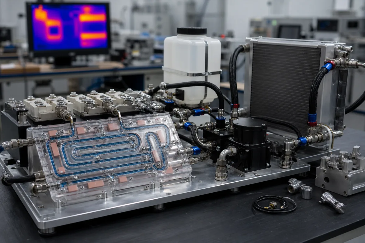
Battery thermal management system (liquid-cooled BTMS unit)
Battery thermal management · Liquid-cooled BTMS units for electric buses, trucks and storage packs: cooling and heating capacity, coolant flow, HV window, refrigerant
A battery thermal management system (BTMS) of this kind is a self-contained unit that keeps a vehicle or storage battery in its temperature window: an electric compressor, condenser and expansion valve chill a water–glycol coolant in a plate heat exchanger (the battery chiller), an electric heater warms it in cold weather, and a pump sends it through the cold plates in the pack. Before asking for prices, fix three things: cooling and heating capacity at your hottest and coldest ambient, the high-voltage window the unit must run from, and how evenly the pack's cells must be held.
Liquid-cooled battery thermal management units for electric buses, trucks, heavy equipment and battery packs, with refrigerant circuit, battery chiller, electric heater, pump and CAN control, plus the pack cold plates they feed. This differs from a stand-alone process chiller that cools machine or process water at a fixed setpoint: those are covered on the Process chiller: capacity, circulation and condensation page. Engine coolant thermostats, cabin-only air conditioners and battery management electronics (BMS) are outside this page.
CNFX editorial research · Sources checked October 12, 2026 · 3 sources
Size cooling and heating capacity for the vehicle and climate
TKT's specification for its 11–12 m electric bus unit (model 10CW) lists cooling of 8–10 kW and optional heating of 6–10 kW, a coolant flow of 45–75 L/min, a weight of 40 kg and dimensions of 780 × 430 × 380 mm, for roof, side or rear mounting. The summary above the table states the cooling as 10 kW, so confirm the rating point with the supplier. TKT gives battery voltage options of DC 220–450 V, 400–750 V and 500–900 V, control power of DC 24 V/10 A or DC 12 V/20 A, CAN control and temperature control of ±0.5 ℃. [1]
TKT states that its BTMS cooling and heating capacity ranges from 3 to 10 kW to suit different commercial vehicles, for ambient temperatures up to 60 °C or down to −20 °C, and that it builds roof-, side- and chassis-mounted battery chillers. It explains the larger unit by vehicle size: a 12 m bus carries more battery packs, so more heat has to be removed or supplied. TKT also writes that the optimal battery operating temperature is 20 to 45 degrees. [1]
Editorial calculation: the coolant temperature change across the pack is heat load ÷ (mass flow × specific heat). Assuming a 50/50 ethylene glycol–water coolant with a density of about 1.07 kg/L and a specific heat of about 3.3 kJ/(kg·K) (assumed property values, not from the cited pages), 10 kW at 45 L/min gives 10 ÷ (0.75 × 1.07 × 3.3) ≈ 3.8 K, and at 75 L/min ≈ 2.3 K. Ask the supplier for the inlet–outlet difference measured on your pack. [1][2]
Give the supplier the pack energy and chemistry, nominal and minimum–maximum voltage, peak charge and discharge power, the pack's cold-plate pressure drop and coolant volume, the hottest and coldest ambient, the mounting position and space, and the CAN messages the BMS will send.
02
Match the high-voltage window, refrigerant and protections
Hebei Nanfeng's 4.5 kW battery thermal management unit (model EHP3.0-3) lists 4.5 kW refrigeration and 5 kW heating capacity, a rated voltage of 320 V DC with overvoltage protection/recovery at 450/470 V DC and undervoltage protection/recovery at 235/250 V DC, a 20–30 V DC low-voltage supply, R1234yf refrigerant, a 34 cc compressor, 50%/50% ethylene glycol/water coolant, a working temperature of −20 ℃ to 50 ℃, IP67 protection, Φ20 mm inlet and outlet pipes, a total mass under 35 kg and CAN2.0 communication. [2]
The same page also says the units are optimised for 450–750 V DC systems, which does not match the 320 V DC rating in the table; confirm which voltage window applies to the model you are quoted. [2]
Nanfeng describes three modes chosen from the battery management system's feedback: refrigeration (compressor and fan on, coolant chilled in the battery cooler), heating (compressor off, electric heater and pump on) and self-circulation (pump only, for low thermal load). It lists protections against overload, undervoltage, overvoltage, overcurrent, overtemperature and abnormal system pressure, with parameters readable over CAN. [2] TKT names IP67 electric parts, including the electric compressor, water pump and connectors, and CAN control to prevent improper operation. [1]
03
Hold cell temperature spread, not just coolant temperature
Wen and co-authors' 2025 review of battery thermal management in electric vehicles describes liquid cooling as coolant, such as water or ethylene glycol solution, carrying heat from the pack to an external heat exchanger. They note that adding ethylene glycol lowers the freezing point and that water–glycol systems carry electrical safety concerns if they leak. [3]
The review reports a simulated air-plus-indirect-liquid design that kept maximum battery temperature below 45 °C at high temperature and high charge–discharge rates, but whose internal temperature gradient exceeded what the authors call the 5 °C safety threshold. It also reports a cold-plate channel layout that cut the maximum temperature difference by 3 K against a Z-shaped layout, and a liquid/heat-pipe hybrid holding 34.1 °C with a 1 °C differential at 2C discharge and 30 °C ambient. [3]
These are research results on specific packs, not ratings of a supplier's unit. They show why a quotation should state the cell-to-cell spread the pack maker will accept and how it will be measured, alongside the unit's coolant temperature control. [3][1]
04
Rooftop, side, rear or chassis mounting and an optional heater
Units differ by where they mount and what they share with the vehicle's climate system. TKT lists roof-, side-, rear- and chassis-mounted units for buses, trucks and heavy equipment. [1] Nanfeng's unit has an optional heater, so the heating function is a separate line in the order. [2]
05
Compressor, chiller plate, heater and pump between the refrigerant and coolant loops
Part
Role
Fix in the order
Electric compressor
Drives the refrigerant circuit; Nanfeng lists 34 cc displacement. [2]
Units are listed for 6–12 m electric buses, trucks and heavy equipment in rooftop and bottom-mounted forms, including a 4.5 kW bus unit and a rooftop air conditioner with integrated battery thermal management; liquid cold plates for EV and energy storage batteries are listed separately.
TKT HVAC
Manufacturing site to be confirmed for the order
Lists battery thermal management units for 6–12 m electric buses, trucks and heavy equipment.
Explore company information and manufacturing capabilities, then discuss the scope of your project with a relevant supplier.
Share this page
Compiled and source-reviewed by the CNFX editorial team.
Each manufacturer above links to the page on that company's own website where the product is listed, with the date we checked it. How we source and review
· Page last updated 13 October 2026
Buyer questions
How much cooling does an electric bus battery unit provide?
TKT's 11–12 m bus unit lists 8–10 kW cooling and 6–10 kW optional heating, and TKT gives a 3–10 kW range across its BTMS units. [1]
What voltage do these units run from?
It depends on the model: TKT offers DC 220–450, 400–750 and 500–900 V; Nanfeng's 4.5 kW unit is rated 320 V DC with protection at 450 V and 235 V. [1][2]
Why specify cell temperature spread?
A 2025 review reports a design that kept cells below 45 °C but exceeded the 5 °C gradient its authors treat as a safety threshold. [3]
Sources and what still needs a direct check
Sources checked 2026-10-12. TKT and Hebei Nanfeng are unit makers and their figures are for the models named. The review by Wen and co-authors summarises published research on battery cooling.