Editorial Technical Reference

Component Feeders

This page explains how Component Feeders is classified within Electrical Equipment Manufacturing. Technical values and manufacturer relationships are research references; confirm the current specification and supplier evidence for each order.

Technical Definition & Core Assembly

Automated devices that supply individual lighting fixture components to assembly stations in a controlled, sequential manner.
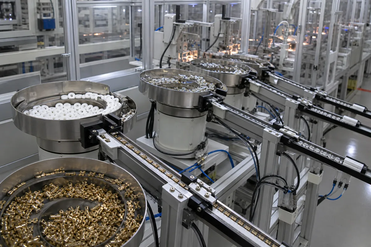
Component Feeders in a manufacturing environment
Representative product image. Confirm appearance and specifications with the manufacturer.

Product Specifications

Technical details and manufacturing context for Component Feeders

Definition
Component feeders are specialized subsystems within automated lighting fixture assembly systems responsible for precisely delivering individual parts (such as bulbs, sockets, wiring, lenses, and mounting hardware) to designated assembly points. They ensure continuous material flow, maintain proper component orientation, and synchronize with robotic arms or human operators to optimize assembly line efficiency and reduce manual handling errors. These feeders are typically integrated into larger assembly lines, where they interface with control systems and downstream equipment. Their design and configuration depend on the specific component characteristics, such as size, shape, and fragility, as well as the required feed rate and accuracy. Common types include vibratory bowl feeders, belt conveyors, and pneumatic systems, each suited to different component types and production volumes. The selection of a component feeder involves evaluating the maximum component size (as specified in the directory reference range), the material compatibility (stainless steel, aluminum alloy, or engineering plastics), and the required orientation and presentation method. Verification of model-specific values, such as feed rate, orientation accuracy, and compatibility with existing control systems, must be confirmed with the legal manufacturer or supplier. Maintenance signals include irregular feeding, jams, or sensor misalignment, which may indicate wear or contamination. Failure boundaries are defined by the feeder's inability to maintain consistent orientation or throughput, often due to component variability or mechanical degradation. Proper maintenance and calibration are essential to ensure reliable operation and minimize downtime.
Working Principle
Component feeders typically operate using vibration, conveyor belts, or pneumatic systems to separate and align parts from bulk storage. Sensors detect component presence and orientation, while programmable logic controllers (PLCs) coordinate timing with downstream assembly processes to maintain consistent workflow. The feeder's mechanism is selected based on component characteristics and required feed rate, with adjustments made for orientation and spacing.
Common Materials
Stainless steel, Aluminum alloy, Engineering plastics
Technical Parameters

What to specify in your RFQ

  • Maximum component size that can be handled in mm

These are the quantities to specify to the manufacturer when sizing or requesting a quote. The manufacturer's own documentation governs the exact figures and applicable standard.

Components / BOM
  • Vibration Bowl
    Separates and aligns components using controlled vibrations
    Material: Stainless steel
  • Feed Track Part
    Guides oriented components to the delivery point
    Material: Aluminum alloy
  • Sensing Module
    Detects component presence, orientation, and potential jams
    Material: Engineering plastics with optical/inductive sensors
  • PLC
    Times each feed to the downstream station so parts arrive when the assembly needs them.

Applied To / Applications

This component is essential for the following industrial systems and equipment:

Industrial Ecosystem & Supply Chain Structure

Complementary Systems
Downstream Applications
Specialized Tooling

Application Fit & Sizing Matrix

Operational Limits
pressure: Atmospheric (non-pressurized system)
other spec: Component size range: 2mm to 50mm, Feed rate: 10-120 components/minute, Power: 24V DC, 100-240V AC
temperature: 5°C to 40°C
Media Compatibility
✓ LED modules ✓ Plastic lens components ✓ Metal housing parts
Unsuitable: High-viscosity adhesives or wet sealants
Sizing Data Required
  • Component dimensions and weight
  • Required feed rate (components/minute)
  • Assembly line interface specifications

Reliability & Engineering Risk Analysis

Failure Mode & Root Cause
Wear and Tear on Feed Tracks
Cause: Abrasive erosion from continuous contact with components, often exacerbated by misalignment, improper component orientation, or the use of abrasive components without adequate track material selection or lubrication.
Actuator or Drive Mechanism Failure
Cause: Fatigue or mechanical overload due to excessive cycling, lack of lubrication, contamination from dust or debris, or electrical issues (e.g., voltage spikes, motor burnout) leading to loss of precise feeding control.
Maintenance Indicators
  • Audible grinding, scraping, or irregular clicking noises during operation, indicating mechanical wear or misalignment.
  • Visual signs of component jamming, misfeeding, or inconsistent feed rates, often accompanied by visible wear marks, debris accumulation, or overheating on feed tracks or actuators.
Engineering Tips
  • Implement a preventive maintenance schedule that includes regular cleaning, lubrication of moving parts, and inspection for alignment and wear, using condition monitoring tools like vibration analysis or thermal imaging.
  • Optimize feeder setup by ensuring proper component orientation, adjusting feed rates to avoid overloading, and using compatible, high-quality replacement parts (e.g., wear-resistant track materials) to reduce abrasive damage and extend service life.

Indicative industry ranges for design and RFQ preparation. Confirm the exact figures and applicable standard with the manufacturer before specifying.

Compliance & Manufacturing Standards

Applicable Standards
DIN EN 60204-1 - Safety of Machinery

Quoted from the published standard.

Manufacturing Precision
  • Feeder Pitch: +/-0.05mm
  • Component Alignment: +/-0.1°
Quality Inspection
  • Functional Cycle Testing
  • Material Composition Verification

Manufacturers of Component Feeders

Manufacturer profiles associated with Component Feeders.

Sourcing Component Feeders from China?
Tell us your specification and target quantity — we will match it against manufacturer records and come back with the factories that fit.
Request manufacturers We manufacture this

Manufacturer listings support early research and capability understanding. They are not certification, ranking, or transaction guarantees.

Share this page
Technical documentation
Request current drawings, revision history, and a signed specification sheet.
Manufacturing capability
Verify equipment lists, process limits, capacity, and representative production evidence.
Inspection readiness
Confirm test methods, calibrated equipment, sampling plans, and traceable reports.
Supplier transparency
Check the legal entity, factory address, ownership, certifications, and direct contacts.

CNFX does not score or rank suppliers. Buyers must verify all claims and documents with the legal manufacturer before ordering.

Supply Chain Compatible Machinery & Devices

Motor Terminal Block

A motor terminal block is a standardized electrical component that provides secure, insulated connection points for motor winding leads.

Explore Specs →
PLC Control System

A digital industrial computer control system that monitors inputs, makes decisions based on a custom program, and controls outputs to automate industrial processes.

Explore Specs →
Control Panel

A centralized interface for monitoring and controlling industrial equipment and processes

Explore Specs →
PLC Control Panel

A centralized interface unit housing the programmable logic controller and associated control components for industrial automation systems.

Explore Specs →

Frequently Asked Questions

What types of components can a component feeder handle?

Component feeders can handle a variety of lighting fixture components such as bulbs, sockets, wiring, lenses, and mounting hardware, provided they fall within the maximum size range specified by the manufacturer. The actual capability depends on the feeder model and its configuration.

How do I select the right component feeder for my assembly line?

Selection involves evaluating the component size, material compatibility, required feed rate, and orientation accuracy. You should also consider the integration with your existing control systems and the physical layout. Always verify model-specific specifications with the supplier.

What maintenance is required for component feeders?

Regular maintenance includes cleaning sensors and tracks, checking for wear on moving parts, and verifying alignment. Signs of needed maintenance include irregular feeding, jams, or sensor misalignment. Follow the manufacturer's guidelines for servicing.

Can component feeders be integrated with robotic assembly systems?

Yes, component feeders are designed to interface with robotic arms and other automated equipment. They use PLCs to synchronize timing and ensure components are presented correctly. Integration requires proper communication protocols and setup, which should be confirmed with the manufacturer.

Data Basis

Editorial classification, named public sources where available, and source-reviewed manufacturer records.

Preliminary Technical Classification
This page supports structured research, RFQ preparation, and supplier evaluation. It does not replace buyer-led supplier qualification, standards review, or technical approval.
Buyer enquiry

Request manufacturing insight for Component Feeders

Ask for use case, specification boundaries, supplier type, and RFQ preparation information for this product.

Where it goes
Straight to the CNFX editorial desk, and to the manufacturer if this product is linked to a claimed profile. Nothing is broadcast to a supplier list.
Your details stay here
We do not sell or rent enquiry data, and we do not add you to a mailing list. Used only to answer this request.
No commission, no middleman
CNFX is a directory. We take no cut of any order and never negotiate on a supplier's behalf.
What we don't claim
A listing is not an endorsement. Qualify every supplier and verify every figure yourself before ordering.

Your business information is used only to process this request.

Thank you! Your message has been sent. We'll respond within 1–3 business days.
Sorry, we couldn't send your message. Please try again, or email us at [email protected].

Need to Manufacture Component Feeders?

Compare manufacturer profiles with relevant product and process capability.

Previous Product
Wire Tensioning System
Last Product
Get QuotesChat