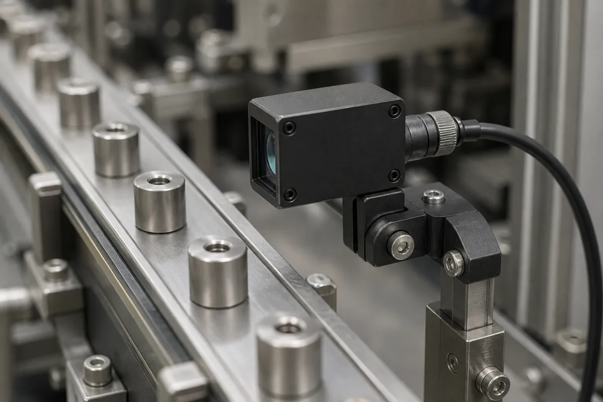
Vision sensing module for a parts-feeder track: checking part orientation and presence with a compact vision sensor
A compact camera-based sensor on an adjustable bracket over a feeder track · field of view at the mounting distance, pixels per part and inspection time per part
Parts leaving a vibratory or linear feeder have to arrive the right way up before a pick-and-place or press takes them. A light barrier can say that a part is there; a compact vision sensor mounted on a bracket over the track can also say which way it faces, by comparing its contour or a pattern with a taught reference. The sensor is a camera, lens, lighting and evaluation in one housing with switching outputs to the feeder's controller. Choosing one comes down to how large the part looks at the mounting distance and how long each check takes.
Self-contained vision sensors (camera, integrated lighting and evaluation in one housing) used at feeder outfeeds and tracks to check presence and orientation of parts and switch a reject or stop signal. Light-barrier, diffuse and other photoelectric switches are covered on the Photoelectric sensor page; counting stations built from inductive proximity switches and through-beam pairs are covered on the Sensor assembly for a part-counting station page. Smart cameras with separate PCs are outside this page.
CNFX editorial research · Sources checked October 12, 2026 · 3 sources
From 9 × 6 mm at 20 mm to 134 × 87 mm at 200 mm: pick the distance that fills the image with a few parts
Wenglor's B50S003 vision sensor has a 736 × 480 pixel monochrome chip with 6 × 6 µm pixels, a 6.4 mm focal distance, autofocus and infrared lighting; its visual field is 9 × 6 mm at 20 mm, 65 × 42 mm at 100 mm and 134 × 87 mm at 200 mm. [1] The di-soric CS 50 switches between two focal lengths: with the 5 mm setting it sees 57 × 43 mm at 50 mm and 110 × 82 mm at 102 mm, and with the 10 mm setting half of each, 29 × 21 mm and 55 × 41 mm. [3]
Editorial calculation for the Wenglor sensor at 100 mm: 65 mm across 736 pixels is about 0.088 mm per pixel, so a feature 1 mm wide, such as a chamfer that tells one end of a bushing from the other, spans about 11 pixels; at 200 mm, 134 / 736 ≈ 0.18 mm per pixel and the same feature spans about 5 to 6 pixels. Mounting closer gives more pixels per feature but fewer parts in the image.
State the part size, the smallest feature that tells right-way-up from wrong, and the distance available above the track; the supplier can then name lens and distance.
02
Contour matching in 30 ms, brightness in 2 ms: what the check costs at the feeder rate
Festo's SBSI object sensor, a 736 × 480 pixel vision sensor at 50 frames per second, lists typical cycle times per tool: 2 ms for brightness, 4 ms for contrast and grey-value threshold, 8 ms for the vernier caliper, 20 ms for pattern matching, and 30 ms for contour matching, position tracking and BLOB analysis. [2] It holds up to 255 inspection programs and 255 detectors. [2]
The Wenglor B50S003 runs at 25 frames per second full frame and offers presence check, pixel and reference-image comparison, tracking, object detection and dimensional accuracy checks. [1] Editorial calculation: 25 fps caps it at 25 images per second, 1500 per minute, before any tool time.
Both sensors connect over M12: the Festo unit has a 12-pin M12 plug for power and I/O, a 4-pin M12 Ethernet socket at 100 Mbit/s and PNP/NPN switchable outputs up to 50 mA, at 24 V DC with up to 550 mA; the Wenglor unit uses a 12-pin M12 connector and an 8-pin X-coded M12 Ethernet socket at 18 to 30 V DC, below 200 mA, with 100 mA switching outputs. [2][1] Both are rated IP67, the Festo unit with its lens protection tube. [2][1]
Check on the part
Festo tool and typical time
Editorial calculation: upper limit, one part per image
These are upper limits from tool time or frame rate alone; trigger delay, exposure, output switching and the reject mechanism lower the real rate, so ask for a timed test on the actual parts.
03
Data for a feeder vision-sensing enquiry
Paste it into your enquiry below or into an email to a maker, then replace every bracket.
Parts: [size; material and surface; feature that shows orientation]
Feeder: [parts per minute; track width; part spacing; stop or moving]
Mounting: [distance available above the track; bracket; ambient light]
Check: [presence, orientation, dimension; reject or stop signal]
Interface: [supply voltage; PNP/NPN outputs; Ethernet protocol; connector]
Explore company information and manufacturing capabilities, then discuss the scope of your project with a relevant supplier.
Share this page
Compiled and source-reviewed by the CNFX editorial team.
Each manufacturer above links to the page on that company's own website where the product is listed, with the date we checked it. How we source and review
· Page last updated 13 October 2026
Buyer questions
How large a field of view does a compact vision sensor see?
Wenglor's B50S003 sees 9 × 6 mm at 20 mm, 65 × 42 mm at 100 mm and 134 × 87 mm at 200 mm. [1]
How long does a contour check take?
Festo lists 30 ms typical for contour matching on its SBSI sensor, against 2 ms for a brightness check. [2]
How many parts per minute can a 30 ms check keep up with?
Editorial calculation: at most about 33 per second, roughly 2000 per minute, before trigger and output delays. [2]
Can one sensor change its field of view?
The di-soric CS 50 switches between 5 mm and 10 mm focal length, halving the field of view, for example from 110 × 82 mm to 55 × 41 mm at 102 mm. [3]
Sources and what still needs a direct check
Sources checked 2026-10-12. Fields of view, pixel counts, frame rates and connections come from the Wenglor B50S003 and Festo SBSI-Q-AF-R3B-F12-W data sheets and the di-soric CS 50 field-of-view sheet; tool cycle times are Festo's typical values. Values apply to the models named.