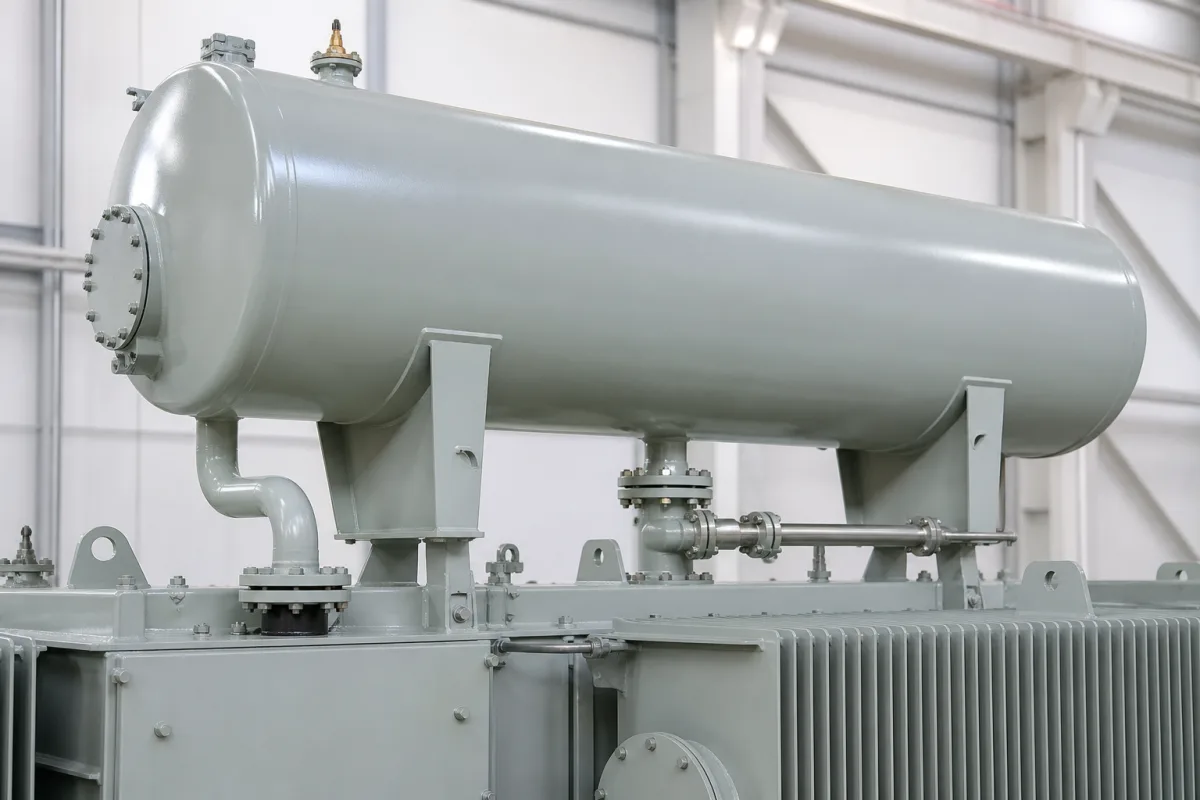
Transformer conservator (expansion) tanks · Free-breathing versus bladder or diaphragm conservators, desiccant breathers and pipe size, magnetic oil-level gauges, bladder-failure and Buchholz relays, and inspection and test intervals
A conservator, or expansion tank, is the oil reservoir mounted above a power transformer's main tank and joined to it by a pipe, so the main tank stays full of oil while the oil expands and contracts with temperature; modern designs add a rubber bladder or diaphragm that separates oil from air, a desiccant breather, a magnetic oil-level gauge and gas-detecting relays. Ask three things first: which oil-preservation design the transformer needs, how the breather, piping and level gauge are sized and fitted, and which relays and test points the conservator must carry.
Conservator (expansion) tanks for oil-filled power and distribution transformers and reactors, with bladders or diaphragms, breathers, level gauges and relay connections. Complete transformers, inert-gas pressure systems, tap-changer conservators sold separately and hydraulic or water expansion tanks are outside this page except where compared.
CNFX editorial research · Sources checked October 12, 2026 · 4 sources
The US Bureau of Reclamation manual FIST 3-30, Transformer Maintenance, describes a free-breathing conservator as an expansion tank above the transformer so the main tank can be completely filled with oil, with breathing taking place away from the main tank. It notes that an oil/air interface remains in the conservator, so oxygen and contaminants eventually reach the insulation, and recommends fitting a bladder or diaphragm conservator, or retrofitting one, together with a desiccant air dryer. [1]
In a bladder or diaphragm conservator the bladder (balloon) or flat diaphragm expands and contracts with the oil and isolates it from the atmosphere, its air side vented through a desiccant dryer so oil and air stay near atmospheric pressure; the oil-level gauge is magnetic, with the float under the centre of the bladder or the indicator arm riding on the diaphragm. Reclamation's practice is to buy conservator designs with bladders for transformers of 115 kV and above and capacities above 10 MVA, and inert-gas pressure designs below these values. [1]
The manual warns that piping between the air dryer and conservator that is too small, or a small or partly blocked dryer intake, lets a vacuum form when oil contracts quickly in falling temperatures, which can form bubbles, operate the Buchholz or bladder-failure relay or pull air past gaskets; it recommends a minimum of ¾ to 1 inch piping and changing the desiccant when about one-third has changed colour. [1]
A bladder maker's manual shows what installation involves. Musthane's operations manual for its MBT rubber air cell (bladder) for transformer conservators describes the sequence. The bag is hung from hooks in the conservator roof, its flange sealed with a gasket, and it is inflated to 10 kPa (0.1 bar) maximum, re-adjusted after 6 hours and then leak-tested for 24 hours. A relief hole must be on the oil side so the bladder can expand freely. It warns never to inflate the bag in free air, because of the risk of bursting, and gives an ideal temperature range of −20 to +70 °C. [2]
The alternative outside this page's scope is a nitrogen blanket. Prolec-GE Waukesha describes nitrogen generator systems that keep transformer tank gas-space pressure between 0.5 and 5.0 psi to protect the oil from oxidation and moisture. Alarms are fitted for low gas-space pressure (below 0.2 psi), high pressure (above 5.5 psi), low storage pressure (below 50 psi) and cabinet temperature, with nitrogen purity above 99%. Comparing the two options helps decide whether a conservator suits the transformer and site. [3]
Editorial calculation: a 1 in pipe has (1 / 0.75)² ≈ 1.78 times the bore area of a ¾ in pipe, so choosing the larger size where the transformer is switched in and out repeatedly or sees large temperature swings reduces the risk of a vacuum forming. [1]
Give the supplier the transformer rating and voltage, oil volume and expansion range, preservation design (free-breathing, bladder, diaphragm), conservator volume and dimensions, bladder material, level gauge type and contacts, breather type and desiccant volume, connection pipe size, Buchholz and bladder-failure relay connections, valves and drain points, coating, mounting brackets and quantities.
02
Fit relays, gauges and test points
FIST 3-30 says the Buchholz relay, found only on transformers with conservators, sits in the pipe between tank and conservator with two oil-filled chambers: gas from overheating, eddy currents or partial discharge collects in the top chamber and drops a float to raise an alarm; a low oil level (empty conservator) operates the bottom float to trip; and a magnetically held paddle in the oil stream trips the transformer on a fault surge, noting that the flow rate at which the paddle trips “is normally adjustable”. [1]
It recommends functionally testing the Buchholz relay every 3 to 5 years with the transformer de-energised by pumping a little air into the top chamber, and describes a bladder-failure (gas accumulator) relay on top of bladder conservators that detects air entering the oil through a damaged bladder, warning never to open its vent without vacuum or pressure equipment. Its inspection table includes checking the diaphragm or bladder for leaks and testing oil-level gauges and alarms. [1]
When filling a bladder conservator, Musthane's manual has the air vent valves at both ends opened and oil pumped slowly from the transformer tank until oil appears at the vents. The vents are then closed, the bag pressure returned to normal, and filling continued until the level indicator reads correctly for the transformer temperature. [2]
Editorial note: ask the conservator supplier for a drawing showing valves to isolate the Buchholz relay, bleed and sampling points, the bladder installation and replacement procedure, and the level-gauge alarm and trip settings.
03
Find conservator tank manufacturers
The companies in the manufacturer list below show this product on their own websites. Confirm the legal seller, factory and scope for your order.
04
Lay out the Buchholz relay pipe to the relay maker's rules
The CEDASPE EB Buchholz relay catalogue, published on Reinhausen's site, places the relay on the pipe between transformer and conservator. The pipe must slope upwards towards the conservator at about 2 to 4 degrees (5 degrees maximum), contain no right-angle elbows, match the relay's oil-passage diameter, and run straight for at least five pipe diameters before the relay and three after it; the relay's petcock must sit below the bottom of the conservator. [4]
The catalogue lists 25, 50 and 80 mm pipe connections and a steady-oil-flow trip setting of 100±15 cm/s, marked standard, with 150±25 and 200±35 cm/s on request. The relay works continuously at 50 kPa internal pressure, withstands 250 kPa for 2 minutes and a vacuum pressure of 2.5 kPa for 24 hours, and operates in oil from −40 to 115 °C and in air from −40 to 70 °C. [4]
Editorial calculation: with an 80 mm pipe the straight runs come to at least 400 mm before the relay and 240 mm after it (5 × 80 mm and 3 × 80 mm). Ask the conservator supplier for a drawing showing pipe size, slope and straight lengths.
Fill the specification fields with values for your transformer
A conservator tank quotation needs values for your transformer. The table explains each field, gives published values where a reviewed source states them, and says what to obtain from the supplier.
Field
What it means and published values
Ask the supplier for
Preservation design
Bladder for ≥115 kV and >10 MVA in one utility's practice. [1]
Explore company information and manufacturing capabilities, then discuss the scope of your project with a relevant supplier.
Share this page
Compiled and source-reviewed by the CNFX editorial team.
Published product pages show what a company offers, not tested performance. Confirm the legal seller, factory, pressure tests and scope for your order. How we source and review
· Page last updated 13 October 2026
Buyer questions
Why use a bladder in a transformer conservator?
The bladder isolates the oil from air while letting it expand and contract, cutting oxygen and moisture contamination that a free-breathing conservator allows. [1]
How big should the conservator breather piping be?
The Bureau of Reclamation recommends a minimum of ¾ to 1 inch to avoid vacuum forming when oil contracts quickly. [1]
When should a Buchholz relay be tested?
Every 3 to 5 years with the transformer de-energised, by pumping a small amount of air into the top chamber. [1]
What pressure is a conservator bladder inflated to during installation?
Musthane's manual for its MBT air cell gives 10 kPa (0.1 bar) maximum, followed by a 24-hour leak test. [2]
How should the pipe to a Buchholz relay be laid?
The CEDASPE EB catalogue on Reinhausen's site asks for a pipe rising about 2 to 4 degrees (5 maximum) towards the conservator, with no right-angle elbows and straight runs of at least five pipe diameters before the relay and three after it. [4]
Sources and what still needs a direct check
Sources checked 2026-10-12. FIST 3-30 is the US Bureau of Reclamation's maintenance manual for its own transformers; its purchasing practice is one utility's choice, not a universal rule. Design for your transformer must come from the transformer maker and applicable standards. Musthane's bladder manual and Prolec-GE Waukesha's nitrogen generator brochure are makers' own documents.