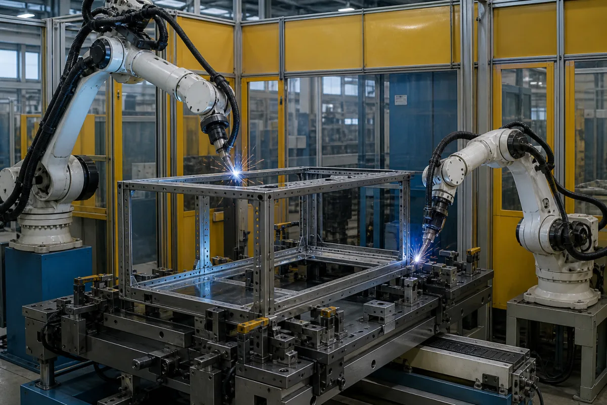
Frame welding station for switchgear and enclosure frames: a reconfigurable clamping bed for 500 to 1000 mm panel widths and two arc-welding robots
Medium-voltage switchgear and enclosure frames · a reconfigurable clamping bed for 500 to 1000 mm panel widths, two arc-welding robots, and the distortion and coating damage that welding does to hollow frame profiles
A medium-voltage switchgear panel or control cabinet starts as a rectangular box frame: vertical uprights and horizontal rails cut from formed steel profiles and joined at the corners. A frame welding station holds those profiles square on a clamping bed and welds the corner and rail joints, here with two arc-welding robots placed on either side of the bed. The questions that decide the station are how quickly the bed can be reset for the next panel width, how far the robots must reach across the frame, and how much heat the profiles and their coating can take before the frame bends or the coating burns off.
Welding stations that assemble and weld the box frames of medium-voltage switchgear panels, control cabinets and similar electrical enclosures from cut profiles: reconfigurable clamping beds, pneumatic locating and clamping modules, robot placement and reach, and distortion and coating damage at the welds. Fixture design principles for welded assemblies are covered on the Welding fixtures page; trailer and semi-trailer chassis welding robots on the Trailer frame welding robot page; pallet-mounted fixtures for vehicle floor pans and toggle clamps on their own pages.
CNFX editorial research · Sources checked October 13, 2026 · 4 sources
One clamping bed for 500, 650, 800 and 1000 mm panels
A single switchgear range already calls for four frame widths: ABB builds its UniGear ZS1 air-insulated switchgear, rated up to 24 kV, in panel widths of 500, 650, 800 and 1000 mm, as single-busbar, double-busbar or back-to-back and double-level versions. [1] A station that serves such a range is reset between widths rather than rebuilt.
A patent from the 28th Research Institute of China Electronics Technology Group describes one way to do this for the welded profile frames of equipment shelters, which it says are large, precise and made in small batches of multiple varieties. A porous grey cast-iron welding platform carries an array of holes that double as air connections. Clamping modules (a flat mounting seat, a 90° rotary clamping cylinder and a 7-shaped pressure head) and positioning modules (a mounting seat, a high-thrust double-shaft double-rod cylinder and an L-shaped reference seat) are pinned to the platform where each frame needs them, and quick-connect air lines link them to 24 V solenoid valves below. [2]
In the same patent a PLC with a touch screen stores the clamping scheme for each frame drawing; for a new drawing the operator divides the frame into separately controlled clamping zones on the screen and sets the order in which they close, and the stored scheme is recalled the next time that frame is made. The patent contrasts this with dedicated tooling, which it calls costly to build and hard to dismantle when changing over, and with manual clamping, which it links to measuring errors and poor frame flatness. [2]
List every frame size the station must take (width, depth, height), the profile section and thickness, how the frame is located (datum corner, holes in the profile), and the target changeover time between sizes.
02
Distortion and coating burn-off on hollow frame profiles
In a patent on frame pieces for switchgear cabinet racks, CES Control Enclosure Systems sets out why it avoids a weld seam to close its hollow profiles. The local heat input that melts the joint introduces thermal stresses that can distort the profile and change the material structure at the seam, so extra steps may be needed to realign it. The weld also burns off coating applied to the flat starting material, locally destroying it and possibly impairing the electrical conductivity and corrosion resistance of the frame. [3]
The same effects apply wherever a station welds frame joints in coated profile. Editorial note: ask the station supplier how the weld sequence and clamping hold squareness and diagonal size while the joints cool, how the frame is checked after release, and how the coating is repaired at the welds and earthing continuity is kept across welded joints.
A switchgear frame also has to hold the panel together in service: ABB states internal arc classification A-FLR for UniGear ZS1 and short-time withstand currents up to 63 kA for the single-busbar version. [1] Editorial note: such ratings belong to the type-tested panel design, so a welded frame should follow the joint details, profile and weld sizes of the design that was tested.
Give the supplier the profile material and coating, the allowed diagonal and flatness tolerance of the welded frame, and the joint details from the panel drawing.
03
Two arc-welding robots either side of the bed: reach and torch access
Yaskawa's AR1440 is one example of an arc-welding robot sized for such cells: six axes, 12 kg payload, 1440 mm horizontal reach and 2511 mm vertical reach on a YRC1000 controller. Yaskawa states that its slim, contoured arm allows dense robot placement and avoids fixture interference, its symmetric wrist gives equal torch access to both sides of a part, and a 50 mm through-hole in the arm carries the torch cable. [4]
Editorial calculation: for a 1000 mm-wide frame, the widest ABB ZS1 width, with one robot on each long side, each robot must weld to the frame's centreline 500 mm in. With 1440 mm horizontal reach, the robot base axis can then be at most 1440 − 500 = 940 mm from the near edge of the frame, before allowing for torch length, torch angle and the height of the joint. [1][4] Joints on the upper rails of a full-height frame sit higher still, so check reach against the tallest frame, not only the widest.
The clamping modules on the bed are also obstacles for the torch: the CETC patent places pressure heads and reference seats at each clamping and positioning point, so the clamping scheme and the robot paths have to be planned together for each frame size. [2]
Ask for a reach study of the largest frame with the clamps in place, showing every joint reached at the required torch angle.
04
Frame sizes, profiles and joints for the welding station quotation
Paste it into your enquiry below or into an email to a maker, then replace every bracket.
Frames: [panel widths, depths, heights; number of variants]
Profiles: [section; thickness; material; coating]
Joints: [corner and rail joints; weld type and size from drawing]
Tolerances: [diagonal; flatness; squareness after release]
Clamping: [datum points; modules per size; changeover time]
Robots: [number; reach study; torch access]
Output: [frames per shift; loading and unloading]
Explore company information and manufacturing capabilities, then discuss the scope of your project with a relevant supplier.
Share this page
Compiled and source-reviewed by the CNFX editorial team.
Each manufacturer above links to the page on that company's own website where the product is listed, with the date we checked it. How we source and review
· Page last updated 13 October 2026
Buyer questions
How many frame widths must a switchgear frame welding station handle?
It depends on the range; ABB builds UniGear ZS1 panels in 500, 650, 800 and 1000 mm widths. [1]
How can one bed take frames of different widths?
A CETC patent pins pneumatic clamping and positioning modules onto a porous cast-iron platform, with a PLC recalling the stored clamping scheme for each frame drawing. [2]
What does welding do to coated hollow frame profiles?
CES cites thermal distortion, a changed material structure at the seam and coating burn-off that can impair conductivity and corrosion resistance. [3]
How far can an arc-welding robot reach across the frame?
Yaskawa's AR1440 has 1440 mm horizontal and 2511 mm vertical reach. [4]
Sources and what still needs a direct check
Sources checked 2026-10-13. ABB's UniGear ZS1 product page, Yaskawa's AR1440 arc-welding robot page, the CES Control Enclosure Systems patent US 9,153,945 B2 on switchgear rack frame pieces, and the CETC 28th Research Institute patent CN 116079313 B on a modular frame welding fixture.