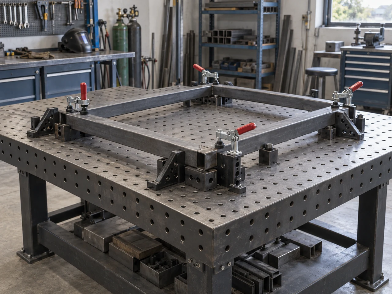
A fixture has two jobs that must be checked separately: locate the unwelded parts, then manage movement as the joint heats and shrinks. The buying decision is whether the assembly can be loaded, welded and removed with the required dimensions after release—not simply whether the clamps hold it tightly.
CNFX editorial research · Sources checked October 10, 2026 · 6 sources
The base carries the references; supports carry the clamp load
The four component groups below describe a functional welding-fixture assembly. Their quantities, part numbers and material grades depend on the actual drawing. They are not a manufacturing BOM for one supplier’s model. Carr Lane supports the locating and force-path explanation; Siegmund illustrates the modular table arrangement. [2][1]
Component / BOM reference
What it does
Material and purchasing detail
Base plate or modular table
Carries the locating/support arrangement and establishes the mounting surface. A modular bore pattern accepts the system’s fixing elements. [1]
Order the actual table/base material, surface treatment, flatness, dimensions and mounting arrangement. The system comparison gives plate dimensions and load guidance, not one universal steel grade. [1]
Locating pins and stops
Establish the position from the specified holes, edges or faces. A relieved second pin can avoid redundant location from two holes. [2][6]
Specify contact geometry, fit, replaceability and the selected catalogue part or drawing. “Hardened steel” alone does not identify a grade, hardness or service replacement. No universal pin material is assigned here.
Clamping arms and contact pads
Seat and retain the work against its supports and locating references. Clamp direction and contact position affect part bending. [2]
Identify the manual/powered mechanism, pad and contact material, force at the working position and mounting hardware. A generic steel label is not evidence for the supplied arm or pad.
Support blocks / rest points
Support the part at the required height and back up clamp force; distinguish a datum contact from a support added for stiffness. [2]
Specify height, adjustment/locking method and contact material. Check the supporting arrangement with the part drawing; no Q235, 45-steel or 40Cr grade is assumed.
For a dedicated station, request the actual assembly drawing and itemised parts list, including actuators, sensors and interlocks where supplied. The four functional groups above do not establish the quantity or safety configuration of an automated cell.
02
Choose the bore system and the complete load configuration
Modular welding tables use a grid of bores and standard bolts, stops and clamps. Siegmund, a German table maker, defines its three systems by bore size [1].
Choose dedicated tooling around the part and welding cell
Mission describes dedicated automotive fixtures and robotic workstations, including interference checks and cycle-time analysis. Compare that scope with a modular table when the work involves repeated datum locations, robot access or variant changeover. A production quantity alone does not establish the economic break-even point; ask each builder to quote the required loading, welding and unloading sequence. [5]
System 16
System 22
System 28
Bore
Ø16 mm
Ø22 mm
Ø28 mm
Grid
50 × 50 mm
100 × 100 mm or diagonal
100 × 100 mm or diagonal
Plate thickness
approx. 11.5–13 mm
approx. 17–19 mm
approx. 24.5–27 mm
Table side height
100 / 150 mm
150 / 250 mm
200 / 300 mm
Recommended load
up to 2,000 kg
up to 3,000 kg
up to 6,000 kg
Typical use
Fine, precise fixtures with little distortion
General metalwork, moderate distortion forces
Heavy steel structures, high clamping and distortion forces
These are Siegmund catalogue comparisons, not universal specifications for every welding table. Recommended loads depend on the type and number of legs. Siegmund also offers connecting elements between systems: different bore sizes are not directly interchangeable, but “only within one system” would overlook those purpose-designed connectors. Confirm the actual table, leg, bolt and accessory configuration. [1]
03
Establish the datums before applying clamp force
Carr Lane’s guide explains workpiece location in a general fixture-design context. Its machining-force examples are not estimates of weld shrinkage force. Apply the locating principles to the weldment drawing and assess the thermal behaviour separately with the welding process. [2][3]
Use the drawing datum scheme
Show which faces, edges and holes establish the coordinate system, and how the fixture and inspection setup relate to those features. [2]
Relieve the second pin where appropriate
Carr Lane describes one round pin with one diamond pin for location from two holes without binding. The diamond pin locates in one axis. Its orientation and fit still belong on the fixture drawing. [6]
Separate intentional pre-bending from an assembly fault
Check how parts seat before welding. Unplanned interference needs investigation; intentionally pre-springing a part is a different, engineered distortion-control method described by TWI. Do not reject every forced offset as a tolerance mistake, or accept an unexplained one as a process setting. [3]
What the guide counts
Carr Lane counts motion in opposite directions separately when it describes twelve degrees of freedom. This describes positive/negative translation and rotation about three axes, not twelve independent coordinates. [2]
The 3-2-1 arrangement
Three primary contacts, two secondary contacts and one tertiary contact establish location in the illustrated scheme. Clamps seat the part against those references. This is a contact arrangement, not a requirement for six separate purchased components on every flexible weldment. [2]
Avoid redundant location
Two fixed locators trying to control the same movement can compete as part sizes vary. Locate from the drawing’s datum features and distinguish required references from additional supports. [2]
Spread the locating contacts
Carr Lane recommends the greatest practical spacing: close spacing magnifies the effect of locator errors. Keep access and part geometry in the layout. [2]
Back up the clamp force
Direct the force toward supported areas so seating the part does not simply bend an unsupported wall. A fixed jaw can also be a locating surface; separating the locating and clamping functions does not mean no component can perform both. [2]
04
Control distortion: pre-set, pre-bend or restrain
TWI, the UK welding research organisation, describes three assembly methods to limit distortion when design changes are not possible [3].
Joint gaps move during welding
TWI notes that "when MMA or MIG welding butt joints, the joint gap will normally close ahead of welding", while with submerged arc welding the joint may open up during welding [3]. Fixtures and tack sequences must allow for the process used.
Plan release and removal
TWI calls for considering balanced welding and easy removal from the fixture. Ask the builder to show the loading, tack/weld and unloading sequence, including the condition at which dimensional acceptance takes place. The part’s position while clamped does not prove its dimensions after release. [3]
ISO 13920 defines welded-construction tolerances, not jig accuracy
The public abstract for ISO 13920:2023, edition 2, covers general linear, angular, shape and position tolerances in four classes, chosen for functional requirements. Individually specified drawing tolerances take precedence. It does not provide a fixture’s positioning accuracy or certify weld quality. The paid numerical tolerance tables were not used for this page. [4]
Method
How it works
Trade-off
Pre-setting
Parts are set at an offset and left free, so shrinkage pulls them into line [3]
Low residual stress and no costly equipment, but the offset is hard to predict and needs representative trial welds [3]
Pre-bending
Parts are pre-sprung, for example with strongbacks and wedges, to counter shrinkage [3]
Effective for angular distortion in thin plate [3]
Restraint
Clamps, jigs and fixtures hold parts during welding [3]
TWI calls it "the more widely practised technique"; some movement on release from locked-in stress, and higher residual stress that can cause cracking in susceptible materials [3]
05
Specify the fixture condition as well as the number
Use these fields to define an order and acceptance check. The modular-system dimensions above are sourced catalogue data; the unfilled fields below require the selected fixture’s drawing or test plan. A clamp, a bare table and a complete welding cell do not share one rating.
Specification field
Unit / basis
What the quotation must identify
Clamping force
N or kN at the work contact
Force, direction, arm position and supporting contact. More restraint is not automatically better distortion control. [2][3]
Clamping stroke
mm
Working travel and clearance for inserting/removing the part. Ask the builder to demonstrate the full motion with the actual assembly.
Positioning accuracy
mm against named datums
The feature measured, permitted error and inspection condition. Do not substitute Mission’s undefined machining-accuracy statement for locator-position acceptance. [5]
Operating temperature
°C; component and exposure stated
Permitted conditions for the selected contacts, actuators and sensors; distinguish local welding heat from room ambient. No category-wide temperature limit is verified here.
Operating pressure
MPa or bar, for powered clamps only
Supply requirement and allowable range from the selected actuator documentation. Manual clamps have no pneumatic supply requirement; no generic 0.4–0.8 MPa range is established.
Material grade
Drawing / component specification
Base, locating contacts, support blocks and clamping elements listed separately, with heat treatment where required. A single steel grade for the whole fixture is insufficient.
Surface treatment
Process and affected surfaces
Identify treatment, masking and dimensional allowance on locating contacts. An anodizing claim alone does not establish a final positional tolerance. [5]
Fixture weight
kg; included equipment stated
Separate tooling mass from workpiece mass and any positioner. Do not equate greater mass with a verified stiffness or load rating.
Base-plate dimensions
L × W × thickness, mm
Provide usable area, mounting pattern and support/leg arrangement. The Siegmund system data illustrate why plate thickness and leg configuration must accompany a table selection. [1]
Adjustment range
mm / degrees; axis identified
Identify the adjustable locator or clamp, locking method and setup references. A general range does not define usable access for every weld.
Repeatability
mm; repeated loading/setup test
Agree the measured features, loading/clamping procedure, number of trials and thermal condition. Repeatable location in the jig is separate from the released welded-part tolerance. [2][3]
Duty cycle
Defined operating cycle / parts per shift
State load, clamp, weld, cool/release and unload timing for the intended process. Do not assign “continuous duty” to an unspecified actuator or station.
06
Require evidence at three levels: tooling, process and released part
Mission’s robotic welding-cell page supplies a real example of a builder’s published scope. Its staffing, site and lead-time figures are undated website statements, not a current capacity audit or a delivery commitment. [5]
Published scope
Arc/spot welding fixtures and workstations, automotive door, roof and bumper tooling, checking fixtures and robotic cells. Confirm the boundary between a fixture-only quote and the complete cell. [5]
Engineering statement
26 welding automation engineers; offline robot programming, cycle-time analysis and interference checks. Request the project-specific layout and review deliverables rather than treating headcount as an acceptance result. [5]
Production statement
Two shifts, six days per week; a stated shortest lead time of 25 days. Obtain the actual schedule for design approval, manufacture, trials and corrections. [5]
Site statement
8,600 m² and more than 230 employees. The web page does not establish the date or current utilisation of that capacity. [5]
Standards claims
The page names ISO 17025 and ISO 9001. Certificates, issuing bodies and scope were not independently checked; these statements do not certify this fixture or the welded part. [5]
Mission also states machining accuracy of 0.008 mm before anodizing and 0.0005 mm after anodizing, without defining the measured feature or method. Preserve those as an unresolved supplier claim, not an expected accuracy improvement after coating. Ask for a locator inspection report against the agreed datum scheme, followed by a trial on representative welded parts measured after release. These are proposed purchase acceptance steps, to be agreed with the builder. [5]
07
Check the locating contacts before blaming weld settings
Carr Lane’s fixture-design guidance calls for accessible, cleanable locating features and avoiding locations where debris interferes with seating. In a welding application, use that principle to plan inspection and cleaning access around the reference contacts. This is a design check, not a prescribed maintenance interval. [2]
Include the locator and support identification in the setup sheet so operators can check that the intended contact is seating. [2]
Ask the builder for wear limits, cleaning methods and replacement/requalification instructions for the selected pins, pads and clamps. These limits are not published for a generic fixture.
When released dimensions drift, inspect seating and setup as well as the welding sequence and restraint. TWI describes both thermal movement and residual-stress release; adding clamp force alone does not identify the cause. [3]
08
Copy a welding-fixture brief
Paste it into your enquiry below or into an email to a maker, then replace every bracket.
Supply boundary: [modular table / dedicated jig / complete welding cell]; quantity [ ]
Part drawing and revision: [ ]; CAD, materials and thicknesses: [ ]
Drawing datums, critical dimensions and acceptance condition after release: [ ]
Welding process and procedure: [ ]; manual / robot: [ ]; access restrictions: [ ]
Part variants and production target: [ ]; loading and changeover method: [ ]
Proposed locating, support and clamp scheme: [ ]; clamp drive / utilities: [ ]
Distortion plan: [pre-setting / pre-bending / restraint]; representative trial parts: [ ]
Modular option: bore system, table size, leg configuration, part load and accessories: [ ]
Required documents: assembly BOM, locator inspection, operating/maintenance instructions: [ ]
Acceptance: agreed fixture checks and trial-weld measurements after release: [ ]
Cell option: positioner / robot / guarding / interlocks / integration responsibility: [ ]
Delivery location, design approval and trial dates: [ ]
Fixture builders, table suppliers and records needing clarification
Dedicated automotive tooling and a modular welding table are different purchases. The companies below are described from the published scope of each website.
DONGGUAN MISSION GAUGE & FIXTURE CO.,LTD.
Hengli, Dongguan, Guangdong, China (published contact address)
Publishes dedicated arc/spot fixtures and robotic welding workstations. Clarify fixture-only versus complete-cell delivery and require project-specific locator and trial-weld acceptance; its machining-accuracy statement is not a welded-part guarantee.
Changzhou, Jiangsu, China (published contact address)
Publishes battery-box/tray welding fixtures and robotic welding integration. Ask for the part-specific support, clamping and robot-access layout rather than treating a battery-box example as a universal fixture.
Botou, Cangzhou, Hebei, China (published contact address)
Lists 3D welding fixture tables and castings. This supports a modular-table offering; a dedicated jig, actuators or a complete robot cell must be separately confirmed.
Xuzhou, Jiangsu, China (published contact address)
Publishes a welding-fixtures product page within vehicle production equipment, but provides little technical specification. The product footer names Henan Xunche while the contact page names China Vehicle Industry; confirm the quotation issuer, manufacturer and exact deliverables.
Describes welding fixture design, positioners and workstation integration, including process engineering. Establish the delivered fixture/cell boundary and local commissioning responsibility. The published contact address is in Taoyuan.
Wanjiang, Dongguan, Guangdong, China (published contact address)
Publishes automotive checking fixtures, welding jigs and body-in-white welding lines. A checking fixture is a separate inspection tool; specify whether the order is for weld tooling, inspection tooling or a complete production line.
Botou, Cangzhou, Hebei, China (published contact address)
Lists 3D welding platforms and welding-fixture workbenches. Confirm the actual table/bore system, supporting structure and included clamps; a table listing does not establish an automated welding station.
Cangzhou, Hebei, China (published contact address)
Publishes 2D/3D welding tables with clamping and locating accessories. Request the configuration drawing and compatible accessory list; the general product range does not establish the load rating of a particular assembly.
Chashan, Dongguan, Guangdong, China (published contact address)
Lists an Alignment Nest (LH & RH) under Welding Fixtures, alongside its broader automotive tooling offering. The detail page does not give a dimensional specification; request the actual jig drawing and trial acceptance, rather than substituting checking-fixture accuracy for a post-weld result.
Explore company information and manufacturing capabilities, then discuss the scope of your project with a relevant supplier.
Share this page
Compiled and source-reviewed by the CNFX editorial team.
Website evidence supports only the stated scope. It is not a factory audit, independent ownership check, certificate validation or proof that a supplier can meet the released-part tolerance. How we source and review
· Page last updated 13 October 2026
Buyer questions
Which modular welding table system should I choose?
Select for part geometry, access, fixture forces and the complete table/support load configuration. Siegmund identifies System 16 by 16 mm bores and a 50 mm grid, and System 28 by 28 mm bores with 100 mm or diagonal layouts. Check the catalogue configuration and compatible accessories, including any approved cross-system connectors. [1]
What is 3-2-1 locating?
Three primary, two secondary and one tertiary locating contacts establish the reference arrangement in Carr Lane’s example; clamps seat the part. It is a locating principle, not a claim that every weldment needs six separate components or no additional support. [2]
Should a welding jig clamp parts as tightly as possible?
No. TWI explains that restraint limits movement but can leave residual stress, movement on release and cracking risk in susceptible materials. The appropriate clamp arrangement depends on the part and qualified welding approach, not a universal maximum force. [3]
Where should clamps press?
Into the locators or supports, so the clamping force does not bend the part. [2]
Sources and what still needs a direct check
Sources checked 2026-10-10. Standards bodies and regulations define the requirements; manufacturer pages show published ranges for those models only. CNFX does not certify products or suppliers.
Actual locator accuracy, repeatability, clamp forces, actuator ratings and material grades for the selected fixture; the category has no universal values.
Mission’s undefined before/after-anodizing accuracy figures, current capacity and stated standards/certificate scopes.
A representative weld trial and the agreed measurement condition after release; ISO 13920’s public abstract does not supply the numerical class tables here.
China Vehicle’s product-page and contact-page copyright names differ. Confirm the contracting entity and fixture manufacturing scope before ordering.
Buyer enquiry
Request manufacturing insight
for Welding Fixture / Jig
Ask for use case, specification boundaries, supplier type, and RFQ preparation
information for this product.
Where it goes
Straight to the CNFX editorial desk, and to the manufacturer if this product is
linked to a claimed profile. Nothing is broadcast to a supplier list.
Your details stay here
We do not sell or rent enquiry data, and we do not add you to a mailing list.
Used only to answer this request.
No commission, no middleman
CNFX is a directory. We take no cut of any order and never negotiate on a
supplier's behalf.
What to include
Share your product specifications, quantity, destination and target delivery date.
Need to Manufacture Welding Fixture / Jig?
Compare manufacturer profiles with relevant product and process capability.