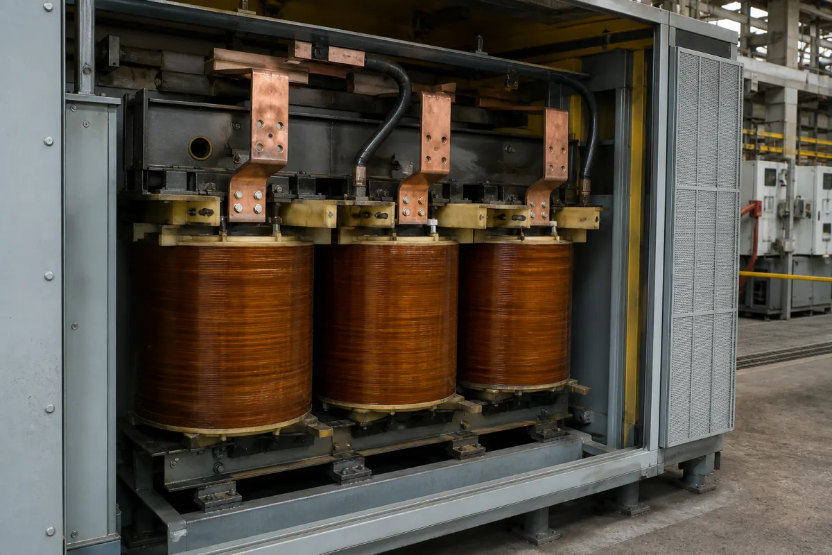
Rectifier main transformer for 12-pulse DC supplies
Main transformer of a rectifier supply · two valve windings 30° apart for 12-pulse, matched leakage inductance, rectifier load class and IEEE C57.18.10 scope
The main transformer of a rectifier power supply converts the network voltage to the valve-side voltage that the diode or thyristor bridges need, isolates the DC system from the AC network and, with two secondary windings displaced by 30°, lets two six-pulse bridges work as a twelve-pulse rectifier. It is built for converter loads, not as a general distribution transformer. Ask three things first: the pulse number and vector arrangement of the valve windings, the valve-side voltage and current for the DC output required, and the rectifier's overload class that the transformer must also carry.
Converter (rectifier) main transformers feeding semiconductor rectifiers for DC traction substations, electrolysis, DC drives and similar dedicated loads: three-winding units with two valve windings, pairs of double-winding units, and phase-shifting arrangements for 12-pulse and higher pulse numbers, dry-type or liquid-immersed. Liquid-immersed and dry-type distribution and power transformers for general utility, industrial and commercial supplies are covered on the Power transformer page. HVDC converter transformers, furnace transformers and instrument transformers are outside this page.
CNFX editorial research · Sources checked October 12, 2026 · 3 sources
KONČAR's KONRECT 3000A-12P traction rectifier is fed from either a three-phase, triple-winding rectifier transformer with two secondary windings, or two identical three-phase, double-winding rectifier transformers; it therefore has two three-phase inputs requiring a 30° electrical phase shift between them, and its dual full-wave diode bridge produces a 12-pulse DC output. [1]
Ladislav Mlynařík and Jaroslav Novák of the University of Pardubice describe a 3 kV DC Czech railway traction rectifier fed by a 22 kV/3 kV twelve-pulse transformer with two secondary windings, one in delta and one in star, and state that both sections must have the same line voltage and leakage inductance. In their model the transformer's line voltage is 2,500 V, and an air choke of 4 mH follows the rectifier. [2]
They explain that twelve-pulse rectification gives a smoother output voltage than six-pulse and that the 5th, 7th, 17th and 19th harmonics of primary current in the two sections are in phase opposition, so the lowest harmonic frequency on the transformer primary is 550 Hz. [2] Editorial calculation: 550 Hz ÷ 50 Hz = the 11th harmonic.
Editorial note: because cancellation depends on the two valve windings being matched, ask the supplier for measured voltage ratio, phase displacement and short-circuit impedance of each valve winding, not only the transformer's overall values.
Send the network voltage and frequency, pulse number, rectifier type (diode or thyristor), DC voltage and current, valve-side voltage per winding, vector group, rectifier load class, cooling, dry-type or liquid-immersed construction, enclosure, installation altitude and ambient temperature, and the standards to be met.
02
Match the rectifier's load class and the standard
The same KONČAR rectifier takes 2 × 518 VAC / 650 VAC three-phase input at 50 Hz with ±10% tolerance and a nominal 2 × 1,115 A, and delivers 660 V DC nominal (600 V at full load, 750 V at no load), 2,000 kW and 3,000 A. Its load class V allows 1.5 × IN for 2 h and 2 × IN for 1 min, that is 4,500 A for 2 h and 6,000 A for 1 min, and it lists HRN EN 60146 and HRN EN 62590. [1] The datasheet does not say which of the two input voltages applies to which arrangement; confirm the valve-side voltage with the rectifier maker.
IEEE C57.18.10-2021 sets practices and requirements for semiconductor power rectifier transformers for dedicated loads rated 100 kW and above, single-phase or three-phase. It excludes static precipitators, high-voltage converters for DC transmission, other nonlinear loads, and mixed loads with more than 10% non-converter fundamental-frequency power. It specifies routine tests, and an informative annex gives examples of load loss calculations for transformers subjected to nonsinusoidal currents. [3]
Editorial note: a transformer sized only for the rectifier's nominal current may not carry its overload class; state the load class and the harmonic current spectrum in the enquiry so that load losses and temperature rise are calculated for converter current, as the IEEE annex describes.
03
Choose one three-winding unit or two matched double-winding units
KONČAR accepts either arrangement for its 12-pulse rectifier; the Pardubice railway case uses the three-winding form with one delta and one star valve winding.
Arrangement
What the source says
Ask the supplier for
One three-winding transformer
Two secondary windings feed two bridges 30° apart. [1]
Vector group and phase displacement.
Two double-winding transformers
Two identical units with a 30° shift between them. [1]
Matching of the two units.
Delta and star valve windings
One secondary in delta, one in star; same line voltage and leakage inductance. [2]
Follow the power path from the MV breaker to the rectifier busbars
In KONČAR's substation description the MV circuit breaker energizes the rectifier transformers, whose valve-side busbars enter the rectifier cabinet from below or above; each part along that path has its own order item.
Quote losses and temperature rise on converter current, not a sine wave
Each rating below has to be stated for the rectifier duty: the IEEE annex calculates load loss for nonsinusoidal current, and the KONČAR load class adds 1.5 × IN for 2 h. Published values appear where a reviewed source gives them.
Company profile lists ZP(T)S, ZPSC and ZPSG-W multi-winding phase-shifting rectifier transformers and rectifier transformers alongside power and dry-type transformers.
Explore company information and manufacturing capabilities, then discuss the scope of your project with a relevant supplier.
Share this page
Compiled and source-reviewed by the CNFX editorial team.
A company profile naming phase-shifting rectifier transformers is not a test record; ask for the vector group, measured phase displacement and routine test report of the unit offered. How we source and review
· Page last updated 13 October 2026
Buyer questions
Why does a 12-pulse rectifier need two transformer windings?
KONČAR's 12-pulse rectifier has two three-phase inputs that require a 30° phase shift, supplied by a three-winding transformer or two double-winding transformers. [1]
What harmonics does a 12-pulse transformer avoid?
The Pardubice study states the 5th, 7th, 17th and 19th primary current harmonics of the two sections are in opposition, leaving 550 Hz as the lowest on the primary. [2]
Which standard covers rectifier transformers?
IEEE C57.18.10-2021 covers semiconductor power rectifier transformers for dedicated loads of 100 kW and above. [3]
Sources and what still needs a direct check
Sources checked 2026-10-12. KONČAR publishes the datasheet of its own traction rectifier, which sets what its transformers must supply; the University of Pardubice paper studies a Czech railway 12-pulse traction rectifier; the IEEE C57.18.10 summary gives the standard's scope.